
Disk array device

a technology of array devices and disks, applied in the direction of memory adressing/allocation/relocation, electrical apparatus casings/cabinets/drawers, instruments, etc., can solve the problems of data loss, data is retreated from the cache, and the response speed is slow, so as to improve the instantaneous power failure durability

Active Publication Date: 2006-11-07
RAKUTEN GRP INC
View PDF8 Cites 63 Cited by
  • Summary
  • Abstract
  • Description
  • Claims
  • Application Information

AI Technical Summary

Benefits of technology

The present invention relates to a storage device that can maintain data integrity and operations even in the event of a power failure. The device includes a logic mounting unit and a memory device mounting packaging unit, which are cooled by a fan. The logic mounting unit includes a channel controlling unit, a disk controlling unit, a cache memory, and a shared memory, while the memory device mounting unit includes multiple memory devices. A battery mounting unit is also included to supply a backup power source during a power failure. The invention also provides a battery mounting unit that is cooled by natural convection of air inside the case body. The technical effects of the invention include optimized data retaining and operation control, improved durability of backup power source, and enhanced instantaneous power failure resistance.

Problems solved by technology

However, if the time of power supply interruption exceeds the capacity of a battery, there are risks such as data loss.
However, in the case of a so-called short power failure occurring by several tens of seconds, once a process to write data on a cache into a HDD is carried out, part of data is retreated from the cache even if electric power is thereafter recovered.
Therefore, response speed becomes slow accordingly.
By the way, since a process to write data on the cache into a HDD requires large consumption of electric power, it is necessary to employ an external UPS (Uninterruptible Power Supply) or the like.
Therefore, restriction to securement and the like of its installation space is unavoidable.

Method used


Image

  • Disk array device
  • Disk array device
  • Disk array device

Examples


Embodiment Construction

[0036]Hereinafter, embodiments of the present invention will be detailed based on the drawings. Note that the same members are denoted by the same reference symbol in principle throughout all the drawings for explaining the embodiments and the repetitive descriptions thereof will be omitted.

[0037]

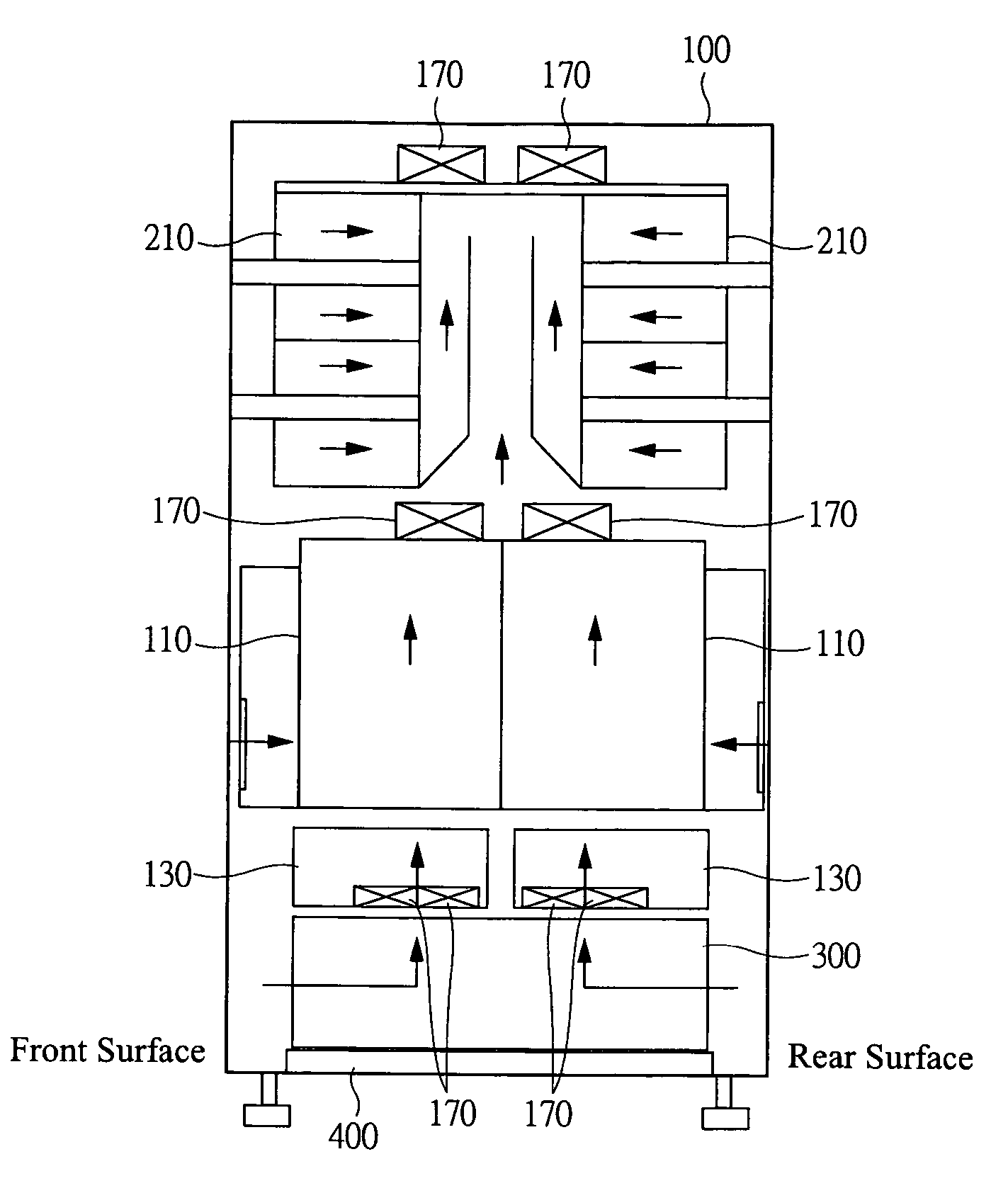
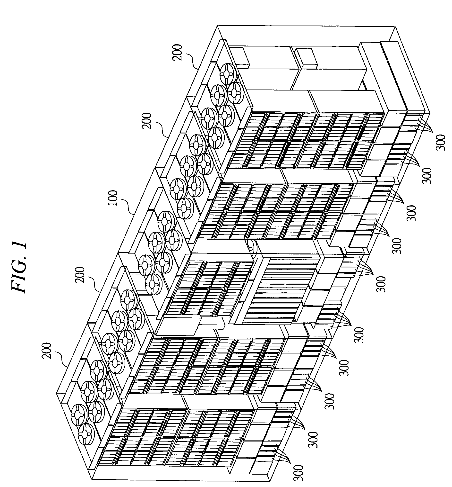
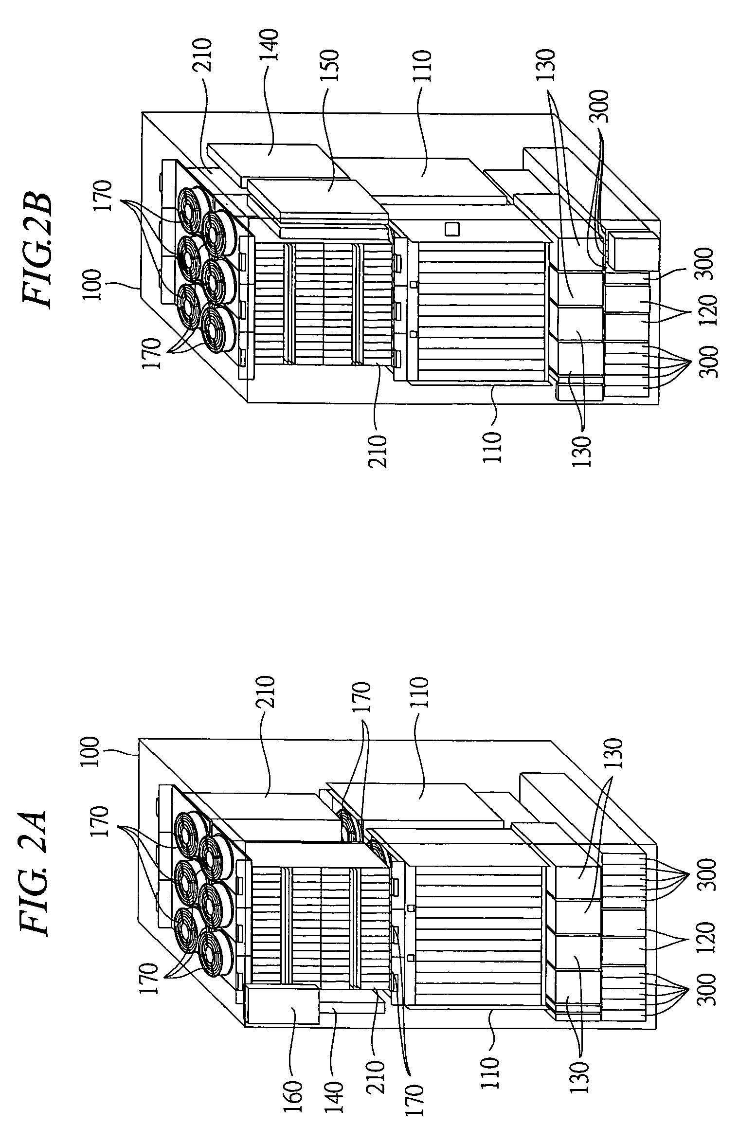
[0038]In reference to FIGS. 1 to 4, an example of an external structure of a disk array device according to an embodiment of the present invention will be described below. FIG. 1 is a diagram showing an example of an external structure of the disk array device according to the embodiment of the present invention. FIGS. 2A and 2B are diagrams showing an example of an external structure of a storage controlling unit, wherein FIG. 2A is a drawing viewed from a front direction and FIG. 2B is a drawing viewed from a rear direction. FIGS. 3A and 3B are diagrams showing an example of an external structure of a storage driving unit, wherein FIG. 3A is a drawing viewed from a front direction and FIG...


PUM

PropertyMeasurementUnit
temperatureaaaaaaaaaa
timeaaaaaaaaaa
instantaneous poweraaaaaaaaaa

Abstract

A disk array device can carry out battery backup including a destage process of data by a battery mounted in a case body of the disk array device and can enhance instantaneous power failure durability to an instantaneous power failure. A logic box mounts a channel controlling unit, a disk controlling unit, a cache memory and a switch; and a hard disk box mounts a plurality of memory devices. A battery box mounts a nickel hydrogen battery for supplying a backup power source at the time of a power failure and is disposed at a lower portion of each case body including the logic box and the hard disk box. The nickel hydrogen battery of the battery box is cooled through natural convection of air created inside the case body by a fan for cooling each of the logic box and the hard disk box.

Description

CROSS-REFERENCE TO RELATED APPLICATION[0001]The present application claims priority from Japanese patent application No. JP 2004-149413 filed on May 19, 2004, the content of which is hereby incorporated by reference into this application.BACKGROUND OF THE INVENTION[0002]The present invention relates to a disk array device and more specifically to a technique effectively applied to data backup by a battery at the time of a power failure.[0003]A conventional disk array device, when power supply interruption such as a power failure occurs, retains data in a volatile memory such as a cache memory by a backup battery.SUMMARY OF THE INVENTION[0004]However, if the time of power supply interruption exceeds the capacity of a battery, there are risks such as data loss. To avoid these risks, electric power supplied from the battery may be used to write volatile data such as a cache into a nonvolatile memory area (hereinafter “destage”). However, in the case of a so-called short power failure o...

Claims


Application Information

Patent Timeline
Patent Type & Authority Patents(United States)
IPC IPC(8): G06F1/16H05K7/00G06F12/08G06F1/18G06F1/20G06F1/30G06F1/32G06F3/06G11B33/10G11B33/12G11B33/14H05K7/20
CPCG06F1/184G06F1/187G06F1/188G06F1/20G06F1/30G11B33/128G11B33/142
Inventor SONE, MASAHIRO
Owner RAKUTEN GRP INC
Learn More