
Ignition safety device and method therefor

a safety device and ignition technology, applied in the direction of anti-theft devices, electric control, engine starters, etc., can solve the problems of user choice to continue operating the motor device in unsafe conditions, fatal consequences, and devices with motors, and achieve the effect of a safety method

Inactive Publication Date: 2006-11-07
ALLISON III ROBERT D
View PDF26 Cites 40 Cited by
  • Summary
  • Abstract
  • Description
  • Claims
  • Application Information

AI Technical Summary

Benefits of technology

"The present invention relates to an ignition safety system and method for vehicles. The system includes a fuse circuit, an ignition circuit, a warning circuit, and a control circuit. The control circuit is connected to both the warning circuit and the fuse circuit. The control circuit controls the operation of the ignition circuit based on the safety condition detected by the warning circuit. The system also includes seatbelt indication means for indicating a seatbelt condition, which is connected to the control circuit to enable or disable the ignition circuit in conformity with the seatbelt condition. The technical effect of the invention is to provide a safer and reliable system for starting vehicles, reducing the risk of accidents and improving safety on the road."

Problems solved by technology

Devices having motors, such as cars, motorcycles, lawnmowers, and chainsaws can be dangerous to operate.
However, these mechanisms for detecting unsafe conditions often only result in a warning being indicated, leaving the user the option to continue operating the motor device in unsafe conditions.
Unfortunately, seatbelt warnings are often ignored, with potentially fatal consequences in the event of a collision.
Such aftermarket devices and installations are often expensive and require altering original wiring for the device to function correctly.

Method used


Image

  • Ignition safety device and method therefor
  • Ignition safety device and method therefor
  • Ignition safety device and method therefor

Examples


Embodiment Construction

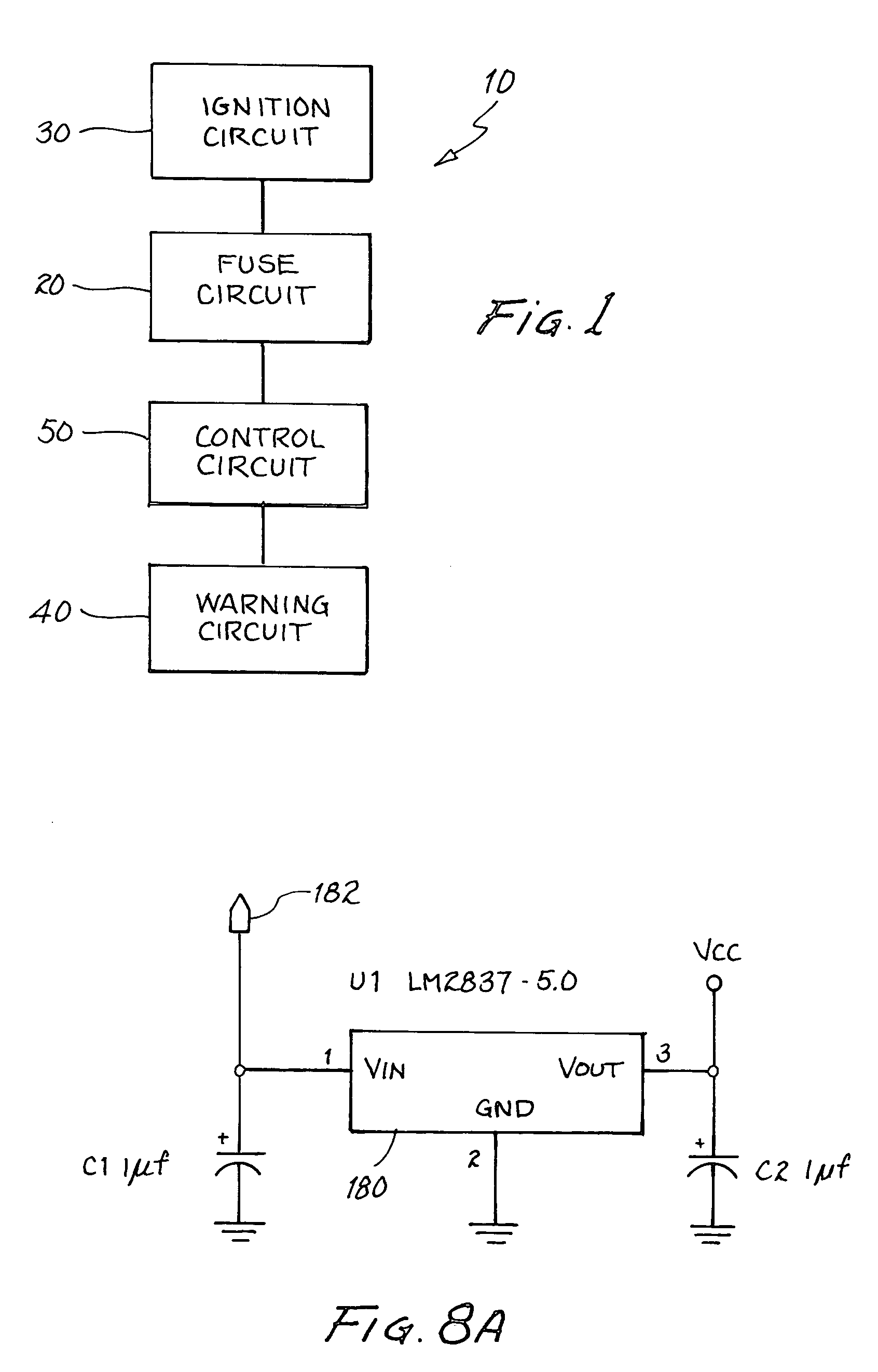
[0024]With reference now to the figures, and in particular FIG. 1, an ignition safety device 10 is shown. The ignition safety device 10 comprises, in combination, a fuse circuit 20, an ignition circuit 30 coupled to the fuse circuit 20 for starting a motor 32, a warning circuit 40 for indicating a safety condition, and a control circuit 50 coupled to both the warning circuit 40 and the fuse circuit 20 for controlling an operation of the ignition circuit30.

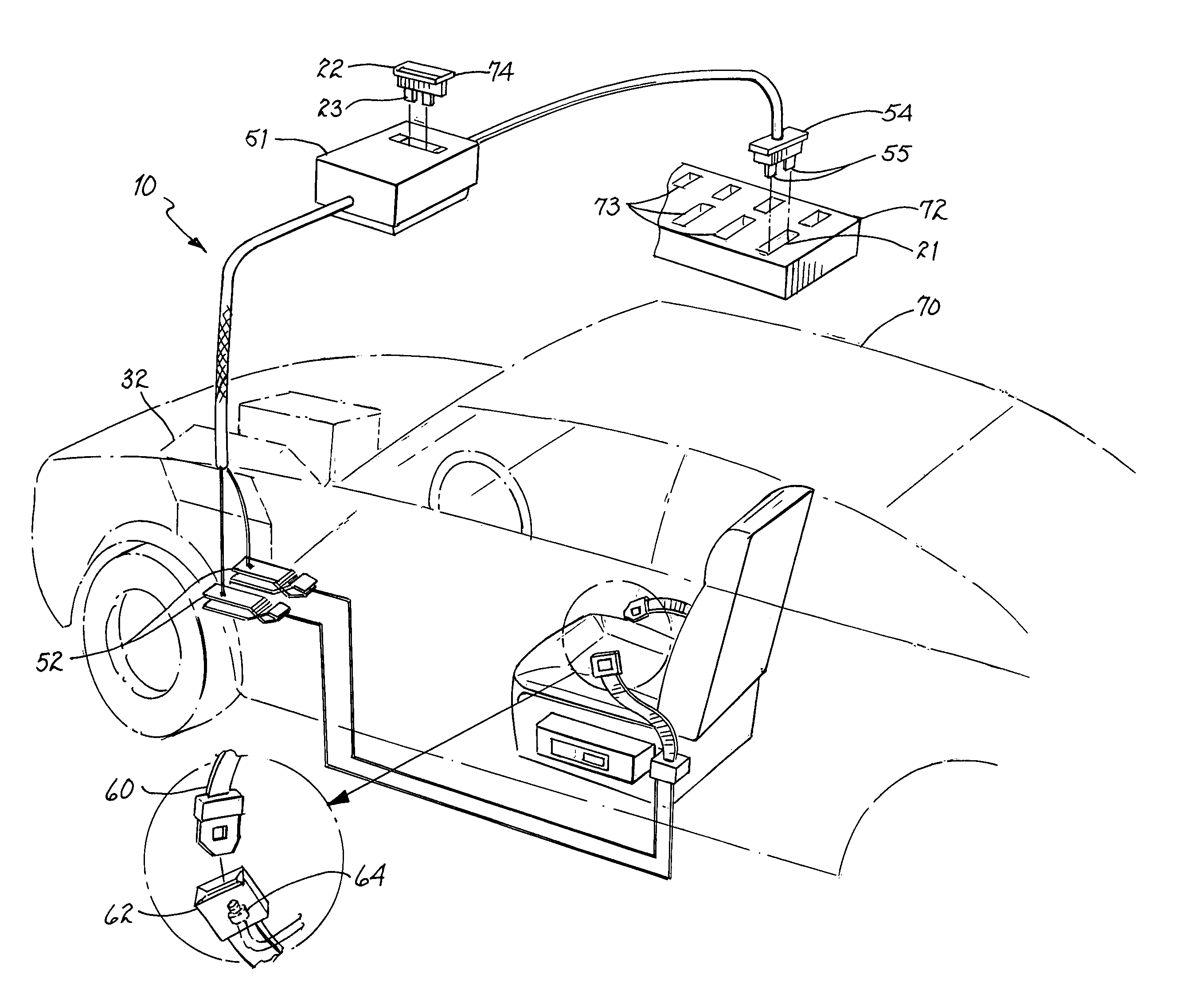
[0025]Referring now to FIG. 2, in accordance with a preferred embodiment of the present invention, the ignition safety device 10 comprises a seatbelt 60, with the safety condition comprising a condition of the seatbelt 60. The safety device 10 further comprises a vehicle 70, and the motor 32 provides power for the vehicle 70. Although the ignition safety device 10 comprises a seatbelt 60 and the safety condition comprises a condition of the seatbelt 60, it is within the spirit and scope of the present invention that the safety devi...


PUM


Abstract

An ignition safety system and method. A control circuit is coupled to a warning circuit indicating a safety condition. The control circuit is further coupled to a fuse circuit to control an operation of a motor ignition circuit in response to the safety condition.

Description

FIELD OF THE INVENTION[0001]This invention relates generally to ignition safety system, and more particularly to a safety system coupled to a fuse housing to control an ignition circuit.DESCRIPTION OF THE RELATED ART[0002]Devices having motors, such as cars, motorcycles, lawnmowers, and chainsaws can be dangerous to operate. Often such motored devices have built-in mechanisms to provide a warning if an unsafe condition exists. For example, automobiles feature indicators that display to a driver if a seatbelt is unfastened or a door is ajar. However, these mechanisms for detecting unsafe conditions often only result in a warning being indicated, leaving the user the option to continue operating the motor device in unsafe conditions.[0003]Unfortunately, seatbelt warnings are often ignored, with potentially fatal consequences in the event of a collision. Drivers and passengers continue to refuse to wear seatbelts, in spite of well-established evidence that seatbelts prevent or reduce i...

Claims


Application Information

Patent Timeline
Patent Type & Authority Patents(United States)
IPC IPC(8): B60Q1/00B60R22/48B60R25/10F02P11/00
CPCB60R22/48B60R25/045B60R25/1003F02D2041/228F02N11/101F02P11/00B60R2022/4816B60R2022/4883
Inventor ALLISON, III, ROBERT D
Owner ALLISON III ROBERT D
Learn More