Preparation of amorphous sulfide sieves
a technology of amorphous sulfide and sieve material, which is applied in the field of catalytic and molecular sieve materials, can solve the problems of difficult and costly formation of such crystalline sieve materials, affecting the reaction efficiency of catalysts, and requiring relatively expensive precursor solution materials and template removal processes, etc., to achieve the effect of increasing the surface area, increasing the synthesis pressure, and increasing the catalytic activity
- Summary
- Abstract
- Description
- Claims
- Application Information
AI Technical Summary
Problems solved by technology
Method used
Image

Examples
example 1
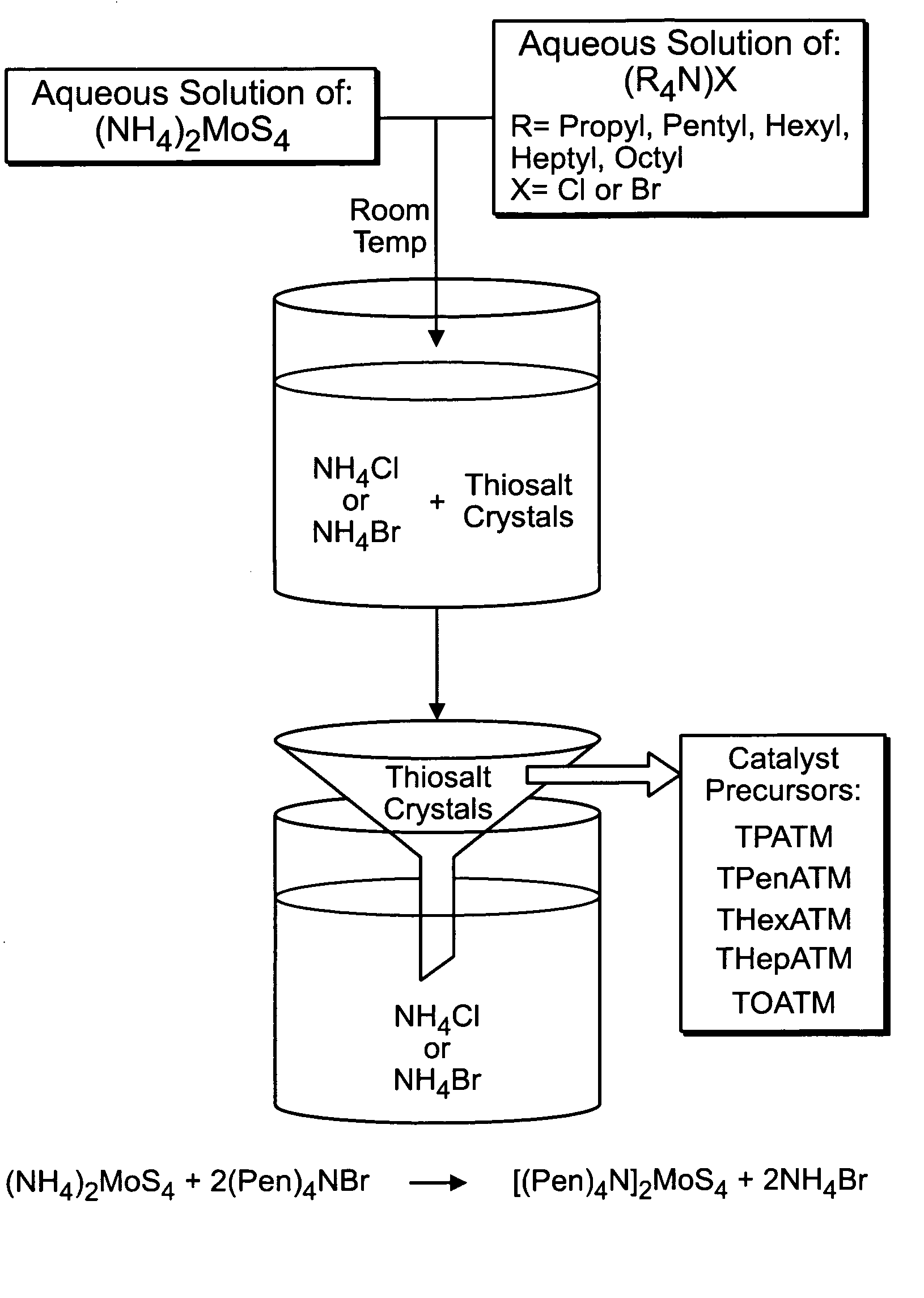
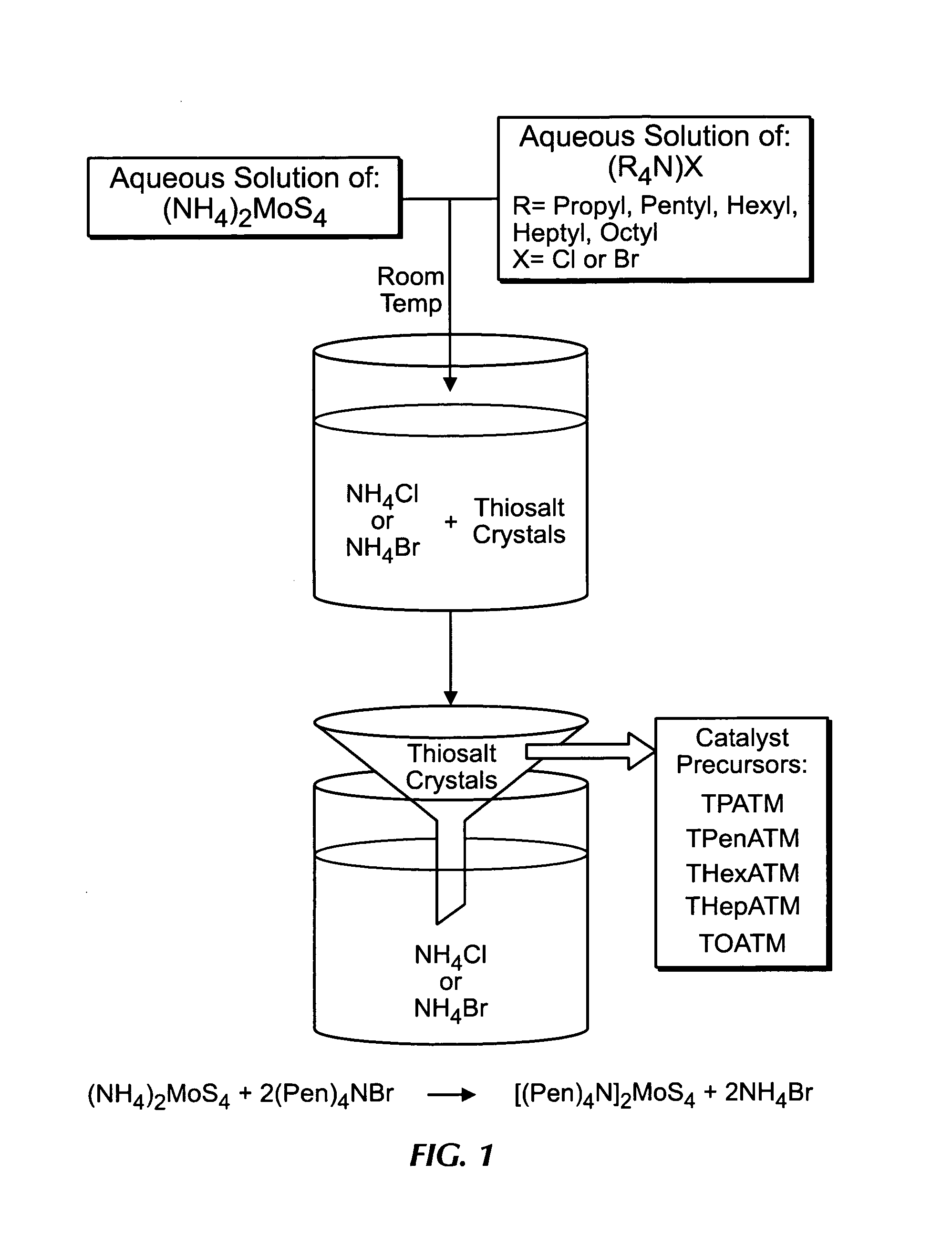
[0114]The tested, produced catalyst showed excellent catalytic activity and selectivity. In one example of producing a MoS2 sieve material of the present invention, the following steps were performed. 6.5 grams of TPenATM was placed inside a flow reactor. While at room temperature, the reactor was pressurized to 500 psi with hydrogen gas. A constant and steady flow of hydrogen gas (1 ml / min) was maintained throughout the entire synthesis process. The reactor temperature was raised to 300° C. at a rate of 2° C. / min to allow sufficient time for the evacuation of the organic components. The reactor temperature was kept at 300° C. for one hour to allow complete synthesis to take place. Finally, the reactor was depressurized to one atmosphere followed by furnace cooling.
Materials and Characterization
[0115]The reactants (Pen)4NBr of 99% purity and cobalt chloride were purchased from Aldrich. The ATM compound was prepared following methods reported elsewhere (Kruss 1884; Corleis 1886).
[011...
example 2
X-Ray Diffraction
[0132]The XRD pattern for MoS2 describes a poorly crystalline structure, as expected. It is important to note that the diffraction profile of poorly crystalline MoS2 is different from that of the crystalline MoS2 (Alonso et al., 1998b; Chianelli, 1982). FIG. 9 describes the XRD pattern of the MoS2 obtained from TPenATM. This pattern is indeed in agreement with those reported for poorly crystalline MoS2 structure (Alonso et al., 2001a; Alonso et al., 1998b). Comparison with FIG. 4 indicates identical results.
example 3
Scanning Electron Microscopy
[0133]The SEM studies on the MoS2 catalysts consistently revealed porous structures. FIG. 10 shows a low magnification shot of an as-synthesized MoS2 from TPenATM. FIG. 11, which is a higher magnification of FIG. 10, shows the fine nature of the surface pores. A high-magnification description of a fresh fracture surface is presented in FIG. 12. The almost uniform nature of the pores as well as the pattern among them is worthy of close observation. It is important to note that the approximately 30 Å mesopores identified by the BET studies (FIG. 13) are not resolved in these SEM micrographs.
PUM
| Property | Measurement | Unit |
|---|---|---|
| temperature | aaaaa | aaaaa |
| temperature | aaaaa | aaaaa |
| temperature | aaaaa | aaaaa |
Abstract
Description
Claims
Application Information
 - R&D
- Intellectual Property
- Life Sciences
- Materials
- Tech Scout
- Unparalleled Data Quality
- Higher Quality Content
- 60% Fewer Hallucinations
Browse by: Latest US Patents, China's latest patents, Technical Efficacy Thesaurus, Application Domain, Technology Topic, Popular Technical Reports.
© 2025 PatSnap. All rights reserved.Legal|Privacy policy|Modern Slavery Act Transparency Statement|Sitemap|About US| Contact US: help@patsnap.com