
Restraint anchorage for a child restraint system

a child restraint and anchorage technology, applied in the field of child restraints, can solve the problems of improper anchorage of child safety seats, child seats, and child seats, and achieve the effects of reducing rework, improving cosmetic appearance, and significantly improving product quality control

Inactive Publication Date: 2006-11-07
MAGNA CLOSURES INC
View PDF41 Cites 17 Cited by
  • Summary
  • Abstract
  • Description
  • Claims
  • Application Information

AI Technical Summary

Benefits of technology

[0007]One advantage of the invention is that the welding of the latch wire to the cross member is eliminated.
[0008]Another advantage of the invention is that the warping or distortions of the transverse member encountered during welding are eliminated.
[0009]Still another advantage is that product quality control is significantly improved and rework eliminated.
[0010]Yet another advantage is that the latch wire may be plated, such as chrome-plated, prior to assembly improving cosmetic appearance, reducing plating costs and increasing wear and corrosion resistance.
[0011]And still another advantage is that the elimination of welding, the cross member may be made from steel, a structural plastic or a carbon fiber material.

Problems solved by technology

The procedure for mounting these child safety seats is awkward and sometimes complex.
As a result, the child safety seat is improperly secured to the seat of the vehicle and the child is not afforded the desired protection in the event of an accident.
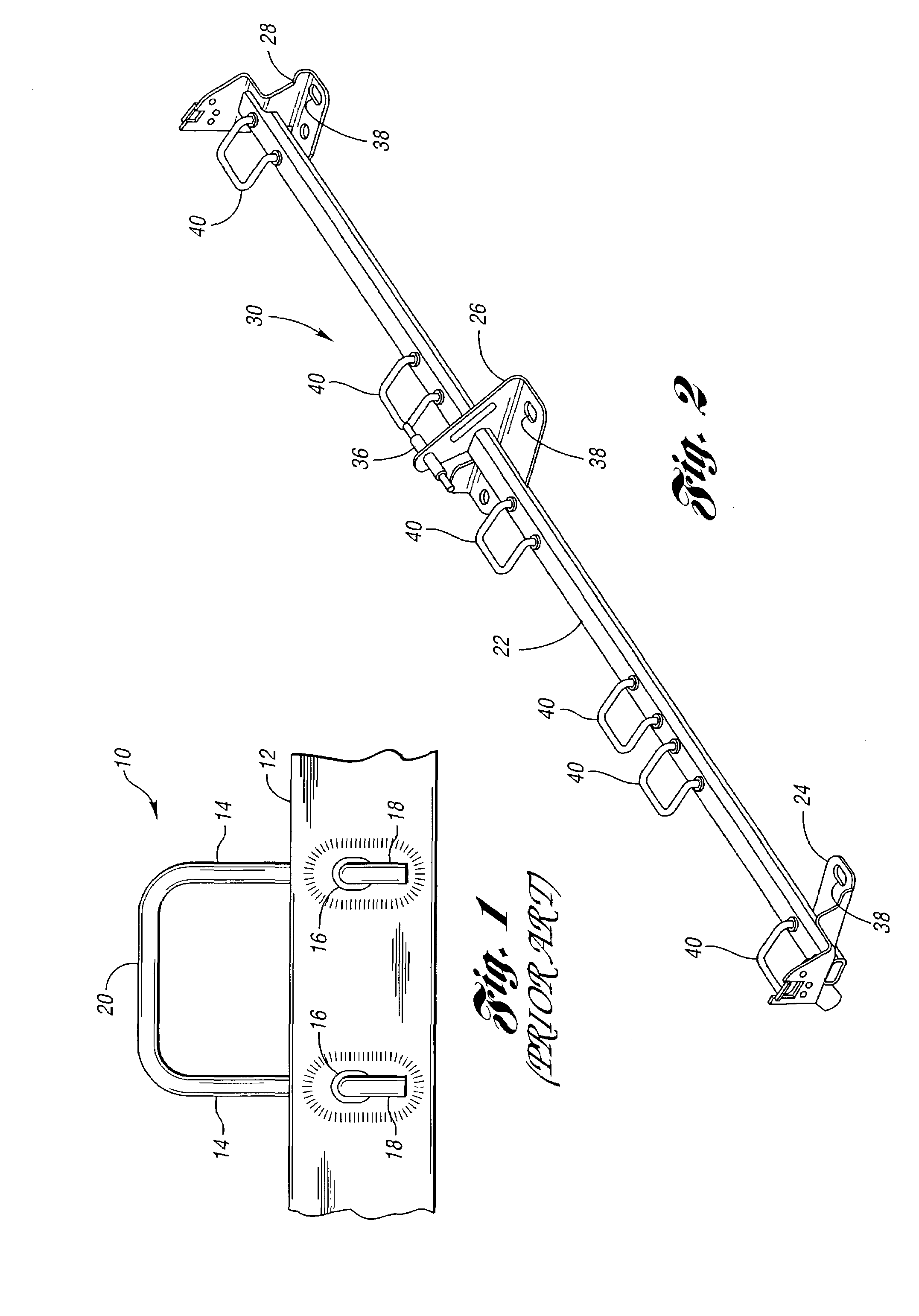
Further, it has been found that the welding of the latch wires 10 to the cross member 12 distort the cross member causing unacceptable assembly to assembly variations from a manufacturing point of view.

Method used


Image

  • Restraint anchorage for a child restraint system
  • Restraint anchorage for a child restraint system
  • Restraint anchorage for a child restraint system

Examples


Embodiment Construction

)

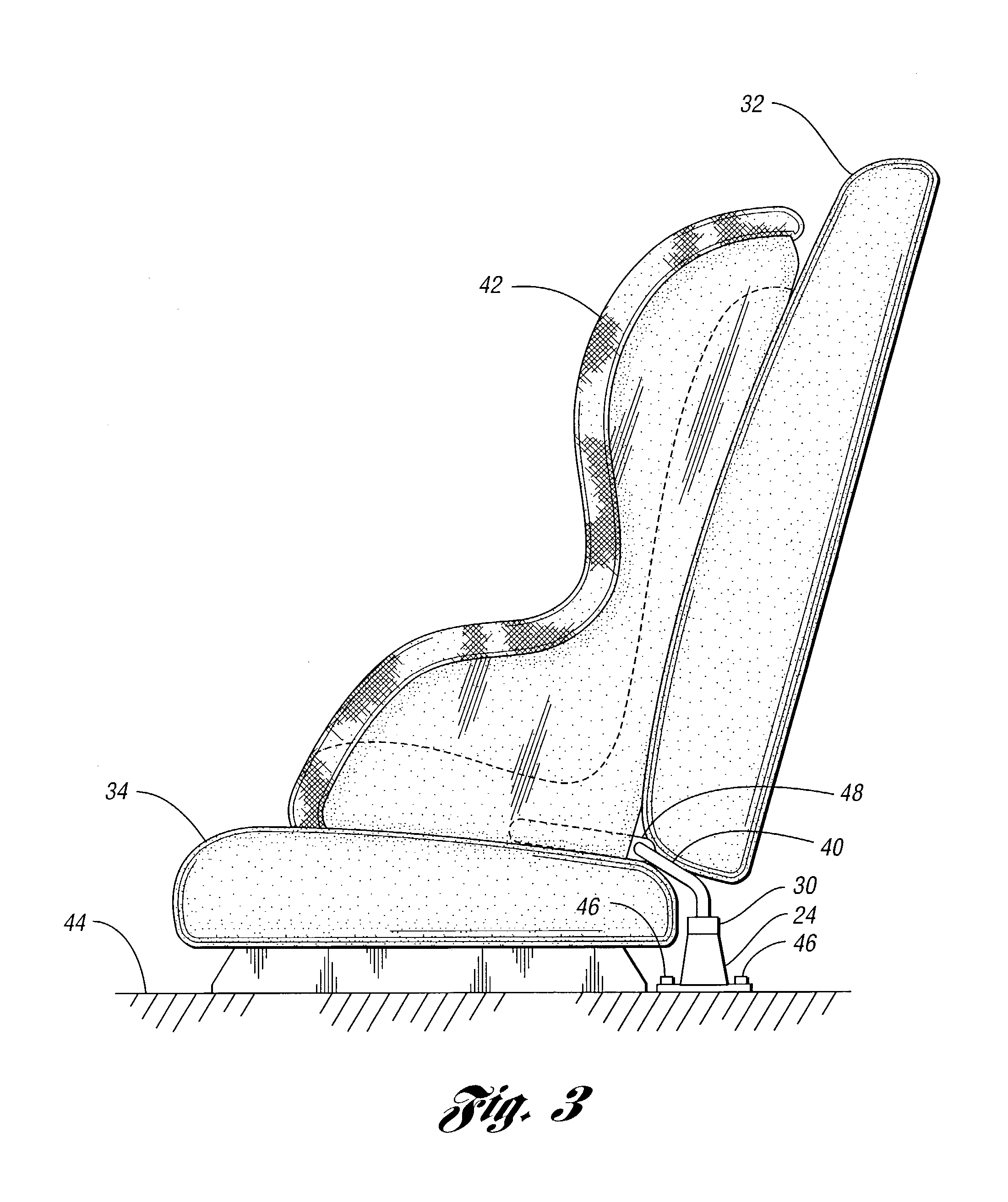
[0019]The anchorage 30 for a child seat safety restraint system according to the invention is shown on FIG. 2. The anchorage 30 comprises a cross-member 22 supported by three mounting brackets 24, 26 and 28 from a structural member of the vehicle (not shown), such as the floor behind the seat of the vehicle. It is to be understood that in many applications only two mounting brackets may be required. The cross member 22 may be made from steel, a structural plastic or a carbon fiber material. The cross member 22 may be a solid bar or a tubular member as illustrated in the drawings. A plurality of U-shaped latch wires 40 are attached to the cross member 22 at selected locations. The illustrated embodiment shows three pairs or sets of latch wires 40 indicative of three possible locations of a child safety restraint seat. These three locations are the left side of the seat, the right side of the seat and the center. It is to be understood that only two or possibly only one set of latch ...


PUM


Abstract

A restraint anchorage for a child safety seat for an automotive vehicle having a cross member disposed behind the vehicle's seat. U-shaped latch wires are attached to the cross member. Collars are provided on the legs of the latch wires which engage one side of the cross members. The ends of the legs which protrude through holes provided in the cross member are peened over to form enlarged heads locking the latch wire to the cross member.

Description

BACKGROUND OF THE INVENTION[0001]1. Field of the Invention[0002]The invention is related to the field of child seat restraints for automotive vehicles and in particular to a restraint anchorage system for securing the child restraint seat to the seat of a vehicle.[0003]2. Background Art[0004]For many years, child safety seats have been required by law for small children riding in automotive vehicles. In the past, these child safety seats have been secured to a passenger seat using the seat belts provided for adult passengers. These seat belts are anchored to one or more structural members of the vehicle. The seat belts are normally threaded through apertures or slots provided in the child safety seat to secure the child safety seat to the seat of the vehicle. The procedure for mounting these child safety seats is awkward and sometimes complex. As a result, the child safety seat is improperly secured to the seat of the vehicle and the child is not afforded the desired protection in t...

Claims


Application Information

Patent Timeline
Patent Type & Authority Patents(United States)
IPC IPC(8): A47D1/10B60R7/00B60N2/28
CPCB60N2/286B60N2/289B60N2/2893B60N2/28B60N2/26
Inventor SMALLWOOD, DAVID J.SHIER, JOHN T.MCLEOD, RONALD D.
Owner MAGNA CLOSURES INC
Learn More