
High-altitude launching of rockets lifted by helium devices and platforms with rotatable wings

a technology of helium devices and rockets, applied in the field of rockets and aerospace engineering, can solve the problems of high stress and pressure, high cost, and high cost of rockets to lift a payload into orbit, and achieve the effects of less violent, less potentially threatening and destructive, and avoiding high stress and pressur

Inactive Publication Date: 2006-11-07
TETRAHEED
View PDF8 Cites 32 Cited by
  • Summary
  • Abstract
  • Description
  • Claims
  • Application Information

AI Technical Summary

Benefits of technology

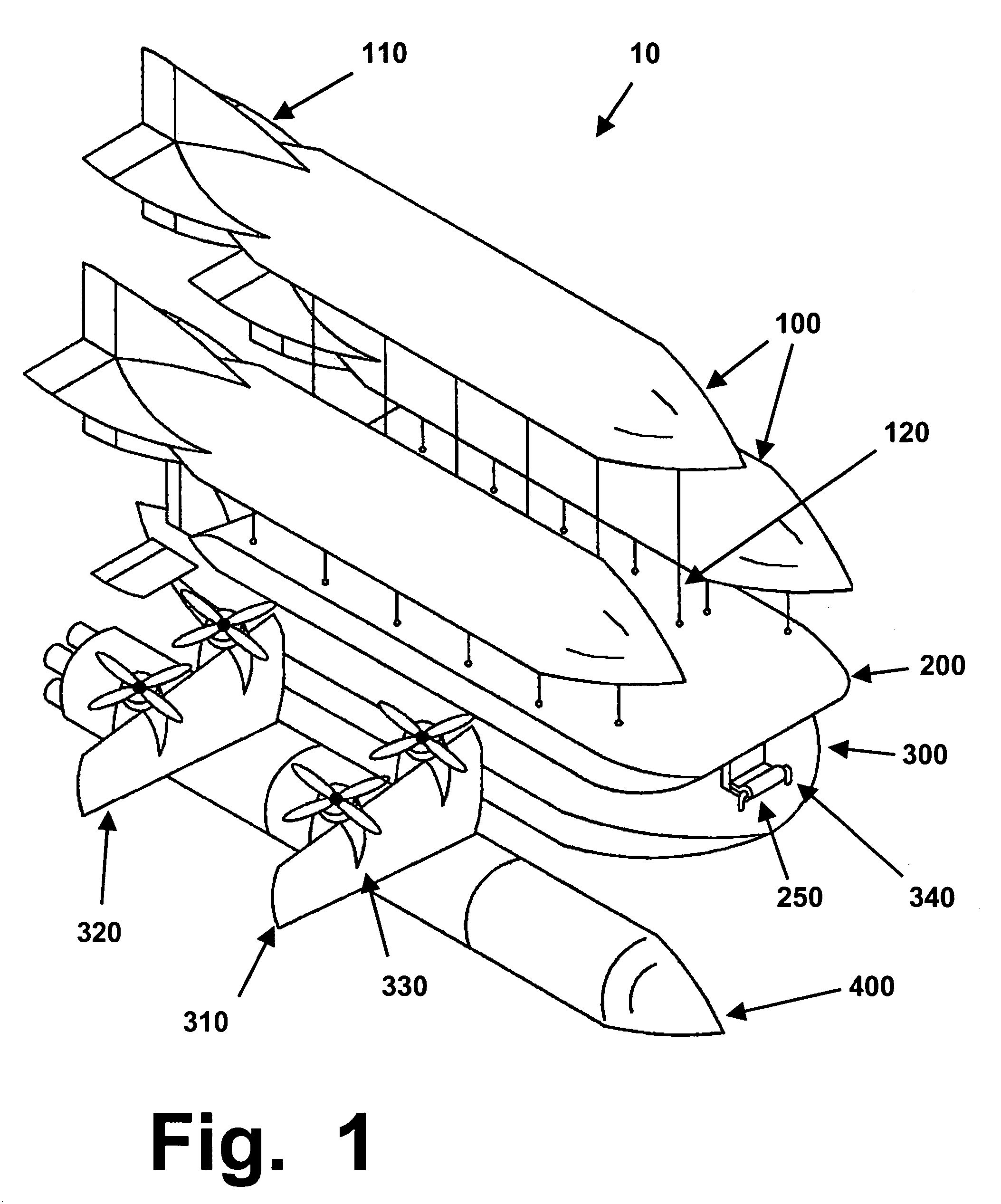
[0045]A four-part system is disclosed for lifting a rocket into the upper atmosphere, and then establishing forward flight at a speed of several hundred miles per hour, before the rocket engines are ignited and the rocket is released from the lifting system. This system enables safer, less expensive, and more efficient launching of rockets and heavy payloads into space, using easily reusable subassemblies. The four main subassemblies of this system comprise, from the top down:

Problems solved by technology

The current method for launching rockets, from a stationary position on a fixed launch pad resting on the ground, is highly inefficient, and requires large, bulky, and very expensive rockets to lift a payload into orbit.
These stresses and strains render rockets more susceptible to failure, and demands very careful maintenance and fairly extensive replacement of parts, between every launch.
A patent application is not the proper forum for an inventor to engage in rhetoric or social commentary; however, readers are asked and urged to at least consider the visual, social, and international implications of this type of lifting and launching system, compared to conventional rocket launchings.
Because of historical and funding factors, rockets and missiles were developed as highly dangerous and destructive weapons.
Even in times of peace, they're closely tied to military uses, and are widely regarded as generally threatening, by anyone who does not live in the nation that launched a new type of rocket (as an example, even when they do not carry outright weaponry into space, they quite often carry spy satellites, military hardware, or other payloads that are designed to advance the interests of the launching nation, rather than the general interests of all humanity).
Even if developed for uses that are ostensibly peaceful, they can be quickly modified to deliver extremely destructive “warheads”.
No one feels reassured when some country that is not a safe and reliable ally decides to create and test bigger, larger, and faster rockets.
By contrast, the systems disclosed herein are not suited at all for aggressive or threatening use.
Since they will rise very slowly, in ways that cannot be hidden from surveillance, they would offer fat, slow, easy targets to defensive weaponry, if a neighboring country or continent feels threatened.
A patent application is not the proper forum for an extended discussion of issues that go beyond the machinery and technology disclosed therein.
Nevertheless, anyone who seriously ponders this invention, and who ponders what it might do to help accelerate and enable the actual construction of permanent colonies on the moon and Mars, should realize that the planning and designing of permanent colonies in space will raise important and unavoidable questions relating to faith, religions, and international relations.

Method used


Image

  • High-altitude launching of rockets lifted by helium devices and platforms with rotatable wings
  • High-altitude launching of rockets lifted by helium devices and platforms with rotatable wings
  • High-altitude launching of rockets lifted by helium devices and platforms with rotatable wings

Examples


Embodiment Construction

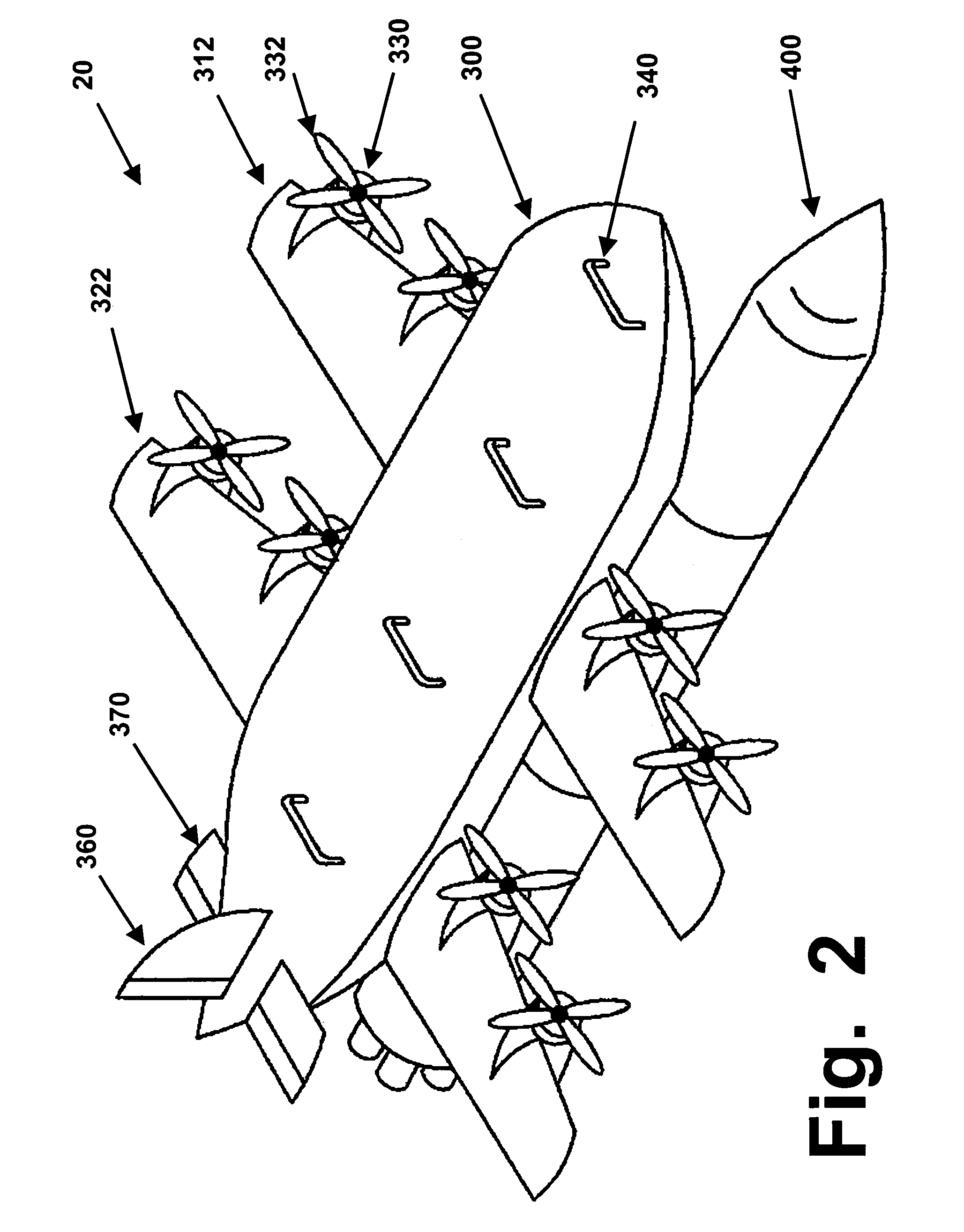
[0053]As summarized above, this invention discloses a system for using helium-filled vessels, and a platform with propeller engines on rotatable wings, to slowly lift a rocket to a high altitude (such as higher than 10,000 meters, or about 30,000 feet). This system is depicted as system 10, in FIG. 1. It can be regarded as having four main subassemblies, or layers. Each of these four main subassemblies is discussed below, under its own subheading.

Helium-Filled Vessels 100

[0054]The uppermost components of the system 10 shown in FIG. 1 comprise large helium-filled vessels 100.

[0055]These vessels can be referred to by any of several terms, including dirigibles, zeppelins, blimps, or balloons. Certain implications of these terms should be recognized, as a preface to using them properly and selecting a preferred term.

[0056]Balloon is the broadest term, since it includes any flexible bladder-type envelope or enclosure that can be filled with a liquid or gas. However, when applied to heliu...


PUM


Abstract

A system is disclosed for lifting a rocket into the upper atmosphere and establishing forward flight at several hundred miles per hour, before the rocket engines are ignited and the rocket is released from the lifting system. The main subassemblies of this lifting system comprise:(1) an array of large helium-filled dirigibles, of a size that can provide hundreds or thousands of tons of lifting force;(2) a tank-holding assembly that will be tethered to the dirigibles, and that will contain pumps and high-pressure tanks, to recapture and store the helium for use in subsequent launches; and,(3) a winged platform, with wings that can be rotated vertically during liftoff, and horizontally to establish forward flight after a desired altitude has been reached, and having conventional aircraft engines on each wing.This system enables safer, less expensive, and more efficient launching of rockets and heavy payloads into space, using easily reusable subassemblies.

Description

RELATED APPLICATION[0001]This application claims priority based on U.S. provisional application 60 / 420,270, filed on Oct. 22, 2002.FIELD OF THE INVENTION[0002]This invention is in the field of rocketry and aerospace engineering, and relates to systems for lifting fully-loaded rockets to high altitudes, and giving them substantial forward speed, before their rocket engines are ignited.BACKGROUND OF THE INVENTION[0003]The current method for launching rockets, from a stationary position on a fixed launch pad resting on the ground, is highly inefficient, and requires large, bulky, and very expensive rockets to lift a payload into orbit. A typical large rocket usually can lift, into orbit, a total payload that weights only about 1 to 3% of the total weight of the fully-loaded rocket. As an example, Saturn V rockets, used to launch the Apollo missions to the moon, weighed roughly 6.2 million pounds when loaded, but they could lift only 285,000 pounds into orbit, and could deliver only 107...

Claims


Application Information

Patent Timeline
Patent Type & Authority Patents(United States)
IPC IPC(8): B64C39/02B64B1/20B64B1/30B64G1/00
CPCB64B1/20B64B1/30B64G1/005B64B2201/00
Inventor KELLY, PATRICK D.
Owner TETRAHEED
Learn More