
System and method for illuminating and reading optical codes imprinted or displayed on reflective surfaces

a technology of optical codes and reflective surfaces, applied in the field of illumination and reading optical codes, can solve the problems of dpm codes being difficult to read (and subsequently decoded) properly, tags or labels may be lost, and coding useless,

Inactive Publication Date: 2006-11-07
SYMBOL TECH INC
View PDF13 Cites 52 Cited by
  • Summary
  • Abstract
  • Description
  • Claims
  • Application Information

AI Technical Summary

Benefits of technology

The solution enables effective illumination and decoding of DPM codes on various surfaces, including polished metallic and glass surfaces, and display screens, with improved contrast and reduced device size, making it suitable for handheld devices.

Problems solved by technology

However, for many applications, such tags or labels may be lost, damaged or altered—rendering the coding useless.
However, as a result of being formed directly onto a wide variety of materials and textures, proper reading (and subsequently decoding) of DPM codes poses a challenge.
The DPM method does not typically provide for the selection of background color or foreground color or reflectivity of the symbol markings, especially in the case of etching and dot-peening.
Therefore, DPM markings often have low and inconsistent contrast, typically resulting in limited code readability.
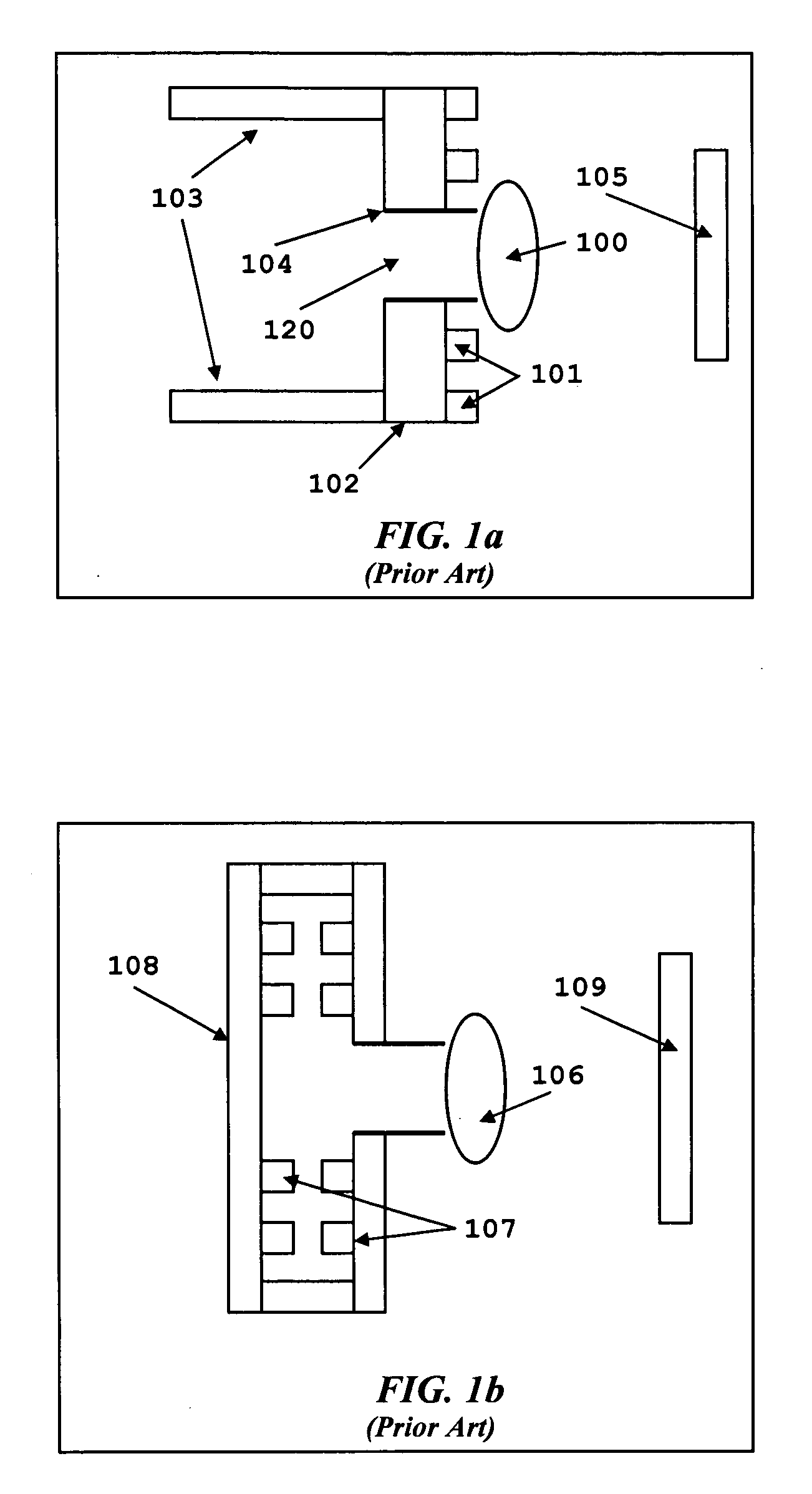
First, this system is relatively large, making the scanner cumbersome and generally unsuitable for integration with handheld computing devices.
The overly thick diffusing plate, however, is inefficient for transmitting light, and consequently requires more powerful illumination than would be necessary with by a light source.
The angle of the extended light source and the reflective diffuser relative to one another and to a front face of the device creates the need for the device to have a substantial depth and to be relatively cumbersome.

Method used


Image

  • System and method for illuminating and reading optical codes imprinted or displayed on reflective surfaces
  • System and method for illuminating and reading optical codes imprinted or displayed on reflective surfaces
  • System and method for illuminating and reading optical codes imprinted or displayed on reflective surfaces

Examples


Embodiment Construction

[0043]The present invention is particularly suited for imaging and decoding optical codes corresponding to a wide range of standardized 1-D and 2-D symbologies. The present invention can be incorporated within various devices, such as handheld computers, mobile phones, etc. for image processing and analysis. The present invention is discussed with a particular emphasis on illuminating DPM codes for the purpose of imaging, reading and decoding the DPM codes, especially DPM codes imprinted or displayed on reflective surfaces such as polished metallic and glass surfaces, and optical codes displayed on display screens, such as LCD display screens of mobile phones, PDAs and laptop computers, and CRT displays used in television sets and computer monitors.

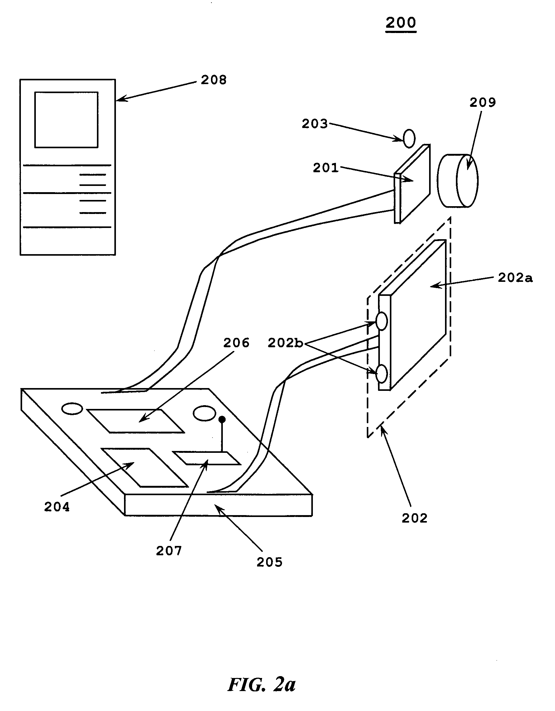
[0044]With reference to FIG. 2a, there is shown an optical code reading system according to the present invention and designated generally by reference numeral 200. The system 200 includes an image sensor 201, such as an array of photo de...


PUM


Abstract

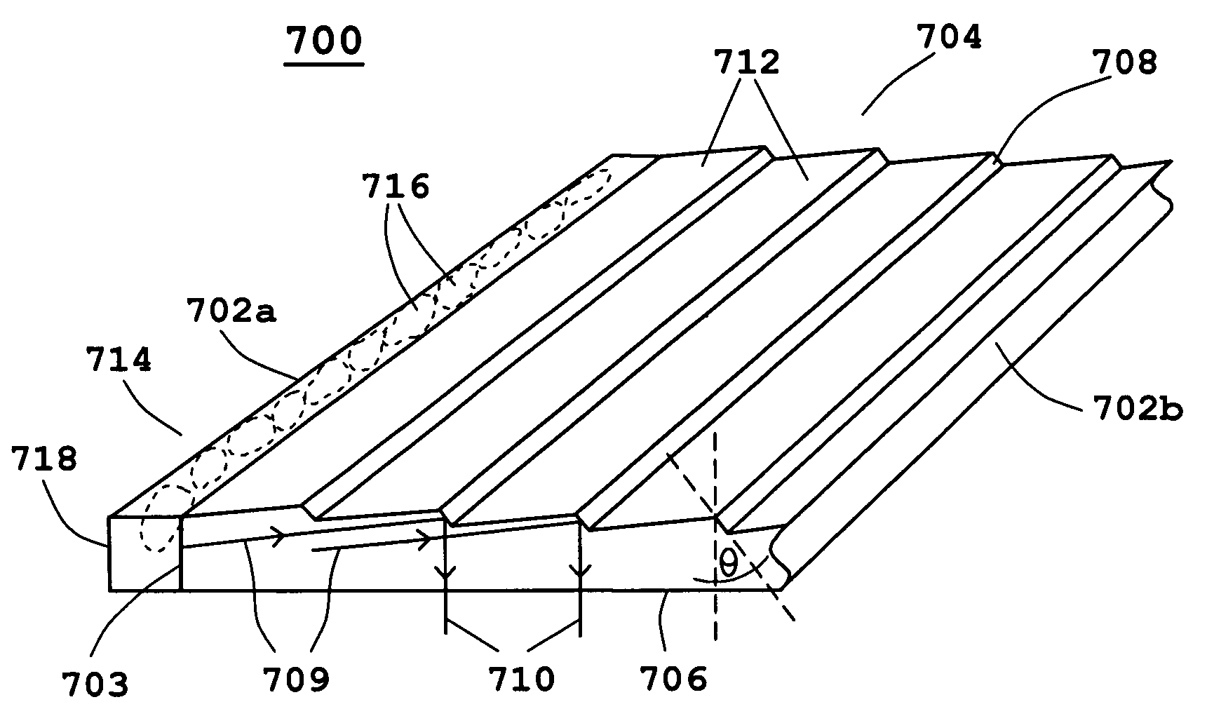
An optical code reading system and method are provided for reading optical codes imprinted or displayed on, or behind, reflective surfaces. The system includes an extended light source, including one of a backlight assembly and a frontlight assembly, emitting an extended-beam light for directly illuminating an optical code, at least one image sensor for sensing light reflected by the optical code and generating signals related to at least one image of the optical code, and at least one processor for processing at least a portion of the signals, generating a decodable image corresponding to the signals, and decoding at least a portion of the decodable image.

Description

CROSS REFERENCE TO RELATED APPLICATIONS[0001]This application is a continuation of U.S. application Ser. No. 10 / 791,018, filed on Mar. 2, 2004 by He et al., the contents of which are incorporated herein by reference in their entirety.BACKGROUND OF THE INVENTION[0002]1. Field of the Invention[0003]This invention relates to illuminating and reading optical codes using optical code reading devices. In particular, this invention relates to a system and method for illuminating and reading optical codes imprinted or displayed on reflective surfaces.[0004]2. Description of the Prior Art[0005]As industry has continued to refine and improve production techniques and procedures, corresponding requirements have been levied for placing identifying data related markings upon components of manufactured assemblies. These markings enable tracking of, for example, the historical stages of a product's manufacture. Further, these markings enable components of complex machinery, such as automobiles and...

Claims


Application Information

Patent Timeline
Patent Type & Authority Patents(United States)
IPC IPC(8): G06K7/10
CPCG06K7/10732G06K7/10742
Inventor HE, DUANFENGJOSEPH, EUGENE B.
Owner SYMBOL TECH INC
Learn More