
Wrist-top computer

a wrist-top computer and data transfer technology, applied in the field of wrist-top computers, can solve the problems of error states and large power consumption of the transmitter device, and achieve the effect of less transmission power and longer operating tim

Active Publication Date: 2006-10-31
SUUNTO OY
View PDF21 Cites 10 Cited by
  • Summary
  • Abstract
  • Description
  • Claims
  • Application Information

AI Technical Summary

Benefits of technology

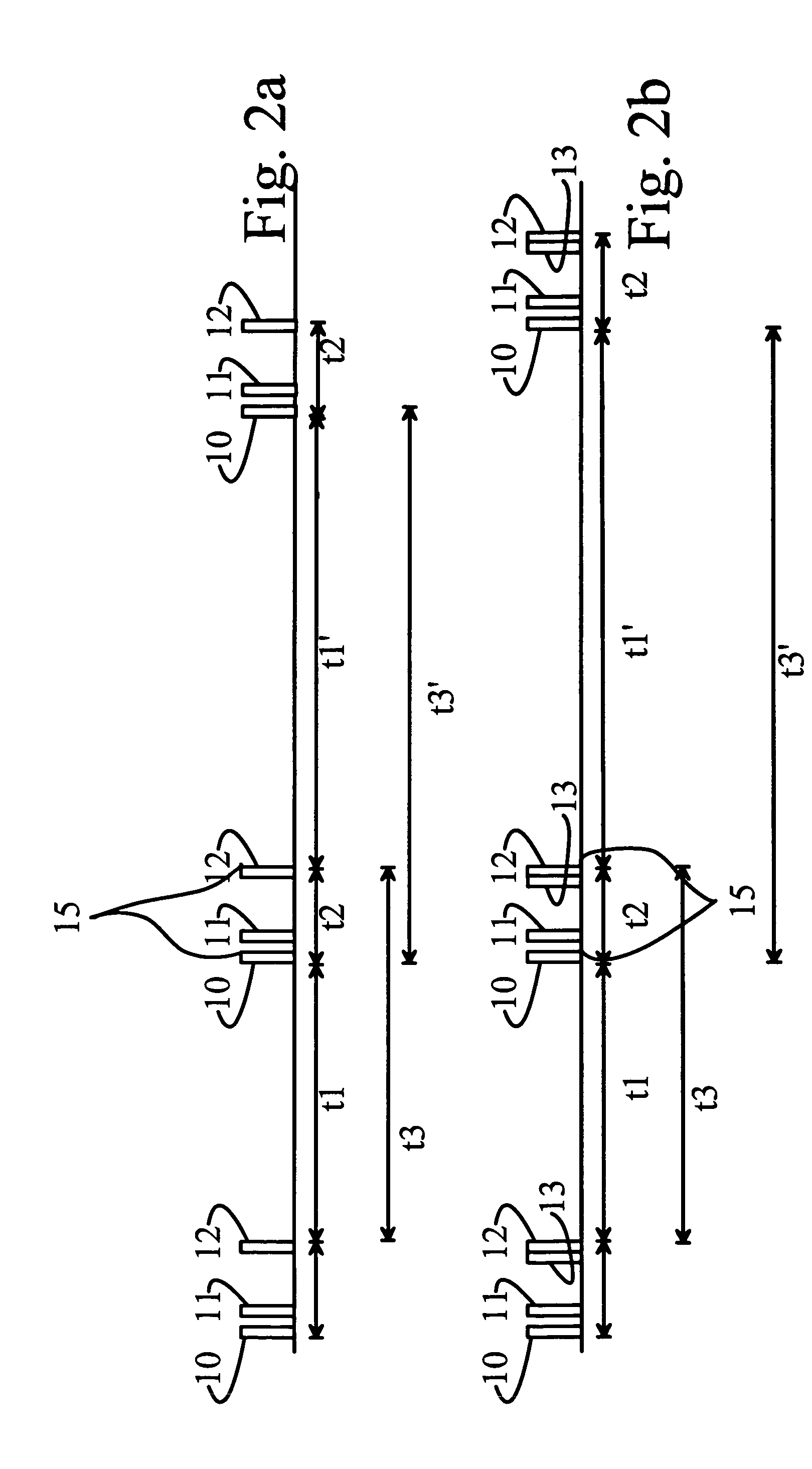
[0012]According to one preferred embodiment of the invention, the transmission power required for the code is minimized by using identifier codes that contain as few 1 bits as possible.
[0015]Compared to the analog coding technique, a considerably larger number of transmitter-receiver combinations can be used close to each other, without uncertainty arising as to the receiver for which each signal is intended.
[0016]Considerably less transmission power is required compared to purely digital transmission, because, other than the starting and ending pulse, the actual measurement data does not contain energy consuming 1-bits. This gives the transmitter device a considerably longer operating time while using the same battery, than when using other techniques.

Problems solved by technology

Implemented using analog technology, this system has been known to lead to error states, if the distance between the identifier pulses of two devices has brought them too close to each other.
Though digital data transfer is very reliable, it does, on the other hand, consume a great deal of power in transmitter devices, which are typically battery powered.

Method used


Image

  • Wrist-top computer
  • Wrist-top computer
  • Wrist-top computer

Examples


Embodiment Construction

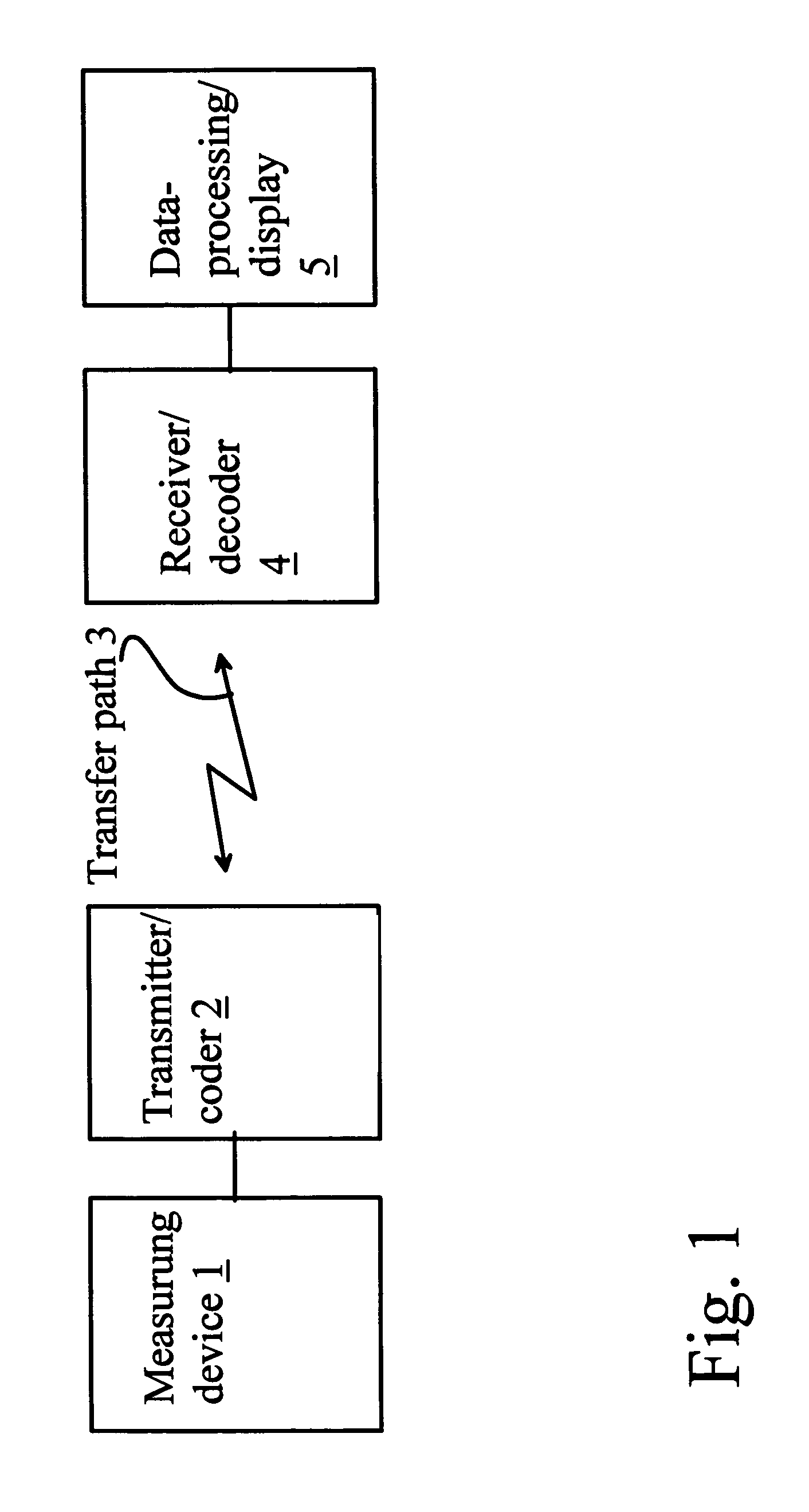
[0023]According to FIG. 1, the apparatus includes a measuring device 1, which is typically a pulse meter attached to the chest by a flexible belt. The pulse meter in question contains electrodes, with the aid of which the pulse of the person is measured. The measuring device 1 can naturally be some other measuring device, such as a manometer of a compressed-air bottle in diving equipment, or alternatively a blood-pressure meter. The measuring device is connected to a transmitter / coder 2, in which the measurement signal is edited into a transmittable form and given a code individuating the transmitter 2. The signal is sent from the transmitter 2 wirelessly over a transfer path 3 to a receiver 4, which also includes means for decoding the code. The transfer path 3 is typically the air between the measuring device 2 located around the chest and a receiver located on the wrist, or alternatively the water between a transmitter attached to the compressed-air bottle and the wristop compute...


PUM


Abstract

A method and apparatus in connection with a wristop computer. According to the method, a desired variable is measured using a measuring unit, the measured variable is equipped with at least one digital codeword and transmitted wirelessly over a transfer channel to a receiver, and at the other end of the transfer channel, the transmitter's signal is identified on the basis of at least one codeword. According to the invention, the digital codeword is transmitted to the receiver together with the measured variable depicted as time-period data (t1 or t3).

Description

CROSS-REFERENCE TO RELATED APPLICATION[0001]The present application claims priority under 35 U.S.C. §119 to Finnish Patent Application No. 2003-1873, filed Dec. 19, 2003, the entire contents of which are hereby incorporated by reference.BACKGROUND OF THE INVENTION[0002]1. Field of the Invention[0003]The present invention relates to a data transfer method for wristop computers. The invention also relates to an apparatus for wristop computers.[0004]2. Description of Background Art[0005]According to the state of the art, wristop computers typically include a transmitter belt connected by a flexible belt to a person's body, and which today typically measures pulse. This measuring device equipped with electrodes transmits a measurement message by radio to a wristwatch-like wristop computer, in which at least part of the received signal is processed and shown on the display of the wristop computer.[0006]Wristop computers can be used to measure not only pulse, but also blood pressure, spee...

Claims


Application Information

Patent Timeline
Patent Type & Authority Patents(United States)
IPC IPC(8): H04B1/034G08B1/08H04Q7/00A61B5/00A61B5/02A61B5/021A61B5/024G08CG08C17/00G08C17/02H04L25/493
CPCA61B5/0002A61B5/02438A61B5/1112A61B5/681A61B5/021A61B2560/0209A61B2503/10
Inventor NIKKOLA, ARI
Owner SUUNTO OY
Learn More