
Method for optimising coverage by reshaping antenna pattern

a technology of antenna pattern and antenna pattern, which is applied in the field of optimising coverage by reshaping antenna pattern, can solve the problems of not always being able to adjust the transmission power, and achieve the effects of reducing the amount of transmission carried, reducing intercellular interference, and reducing the transmission power of terminal equipmen

Inactive Publication Date: 2003-01-21
HANGER SOLUTIONS LLC +1
View PDF12 Cites 6 Cited by
  • Summary
  • Abstract
  • Description
  • Claims
  • Application Information

AI Technical Summary

Benefits of technology

The object of the present invention is to optimise the coverage area of a base station in a situation where the base station does not know the location or direction of a terminal equipment. If, on the other hand, the base station knows the location or direction of the terminal equipment, the coverage area and the shape of the lobe can be further optimised more effectively than in the prior art.
Major advantages are achieved by the method of the invention. The orientation of the antenna lobe of the base station reduces the amount of transmission carried outside the cell, and so intercellular interference is also reduced. When the antenna lobe is oriented toward a terminal equipment, the transmission power of the terminal equipment can also be minimised, which reduces the overall interference level both within a cell and in adjacent cells.

Problems solved by technology

The adjustment of the transmission power, however, is not always possible.
The problem with horizontal orientation of the antenna lobe is that the base station has to know in what direction or location the terminal equipment is.

Method used


Image

  • Method for optimising coverage by reshaping antenna pattern
  • Method for optimising coverage by reshaping antenna pattern
  • Method for optimising coverage by reshaping antenna pattern

Examples


Embodiment Construction

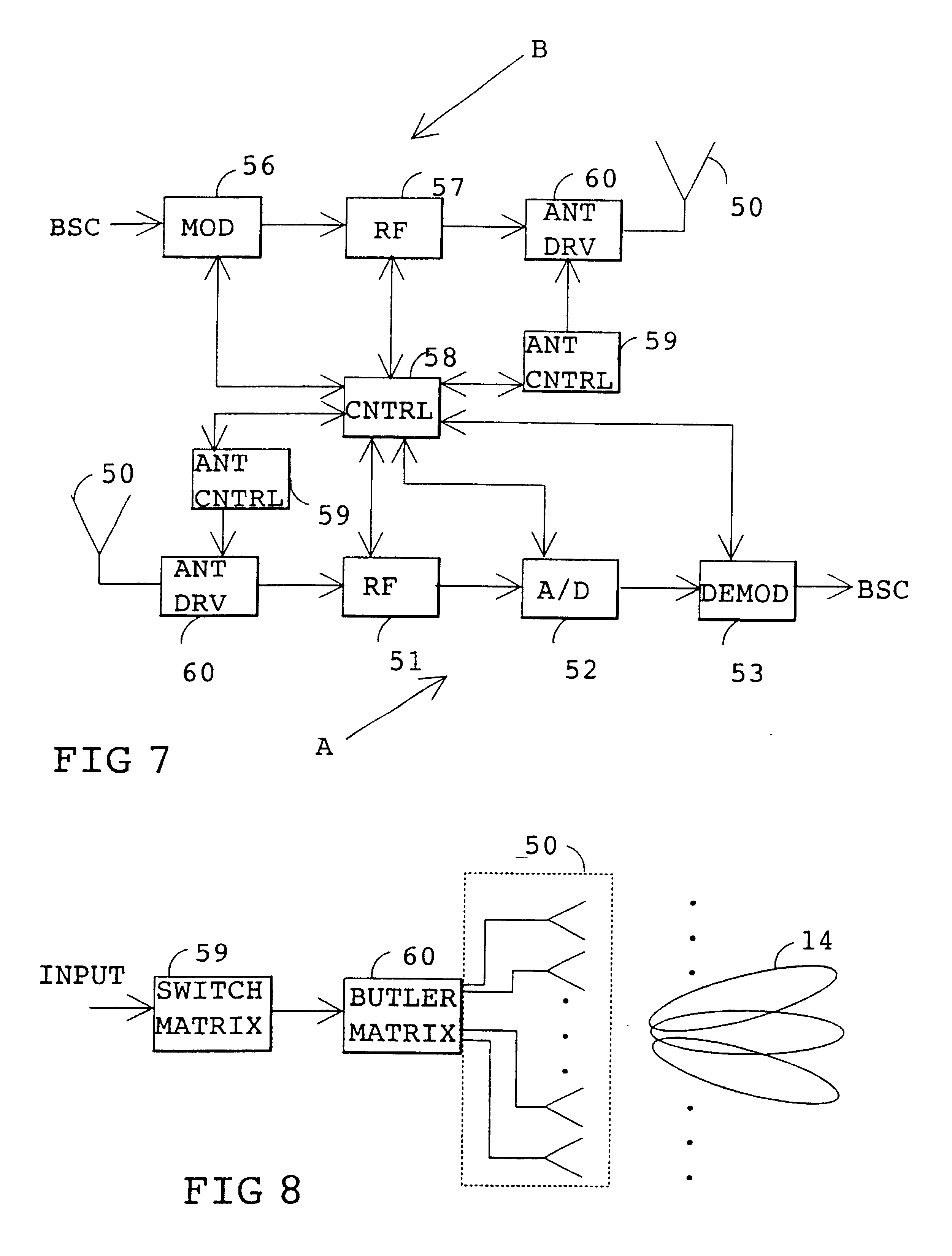
The solution provided by the invention can be used in digital and analogue radio systems based on time division. The invention is here described mainly with reference to the GSM cellular radio system operated by a digital TDMA method. The applicability of the invention, however, is not limited to the GSM system.

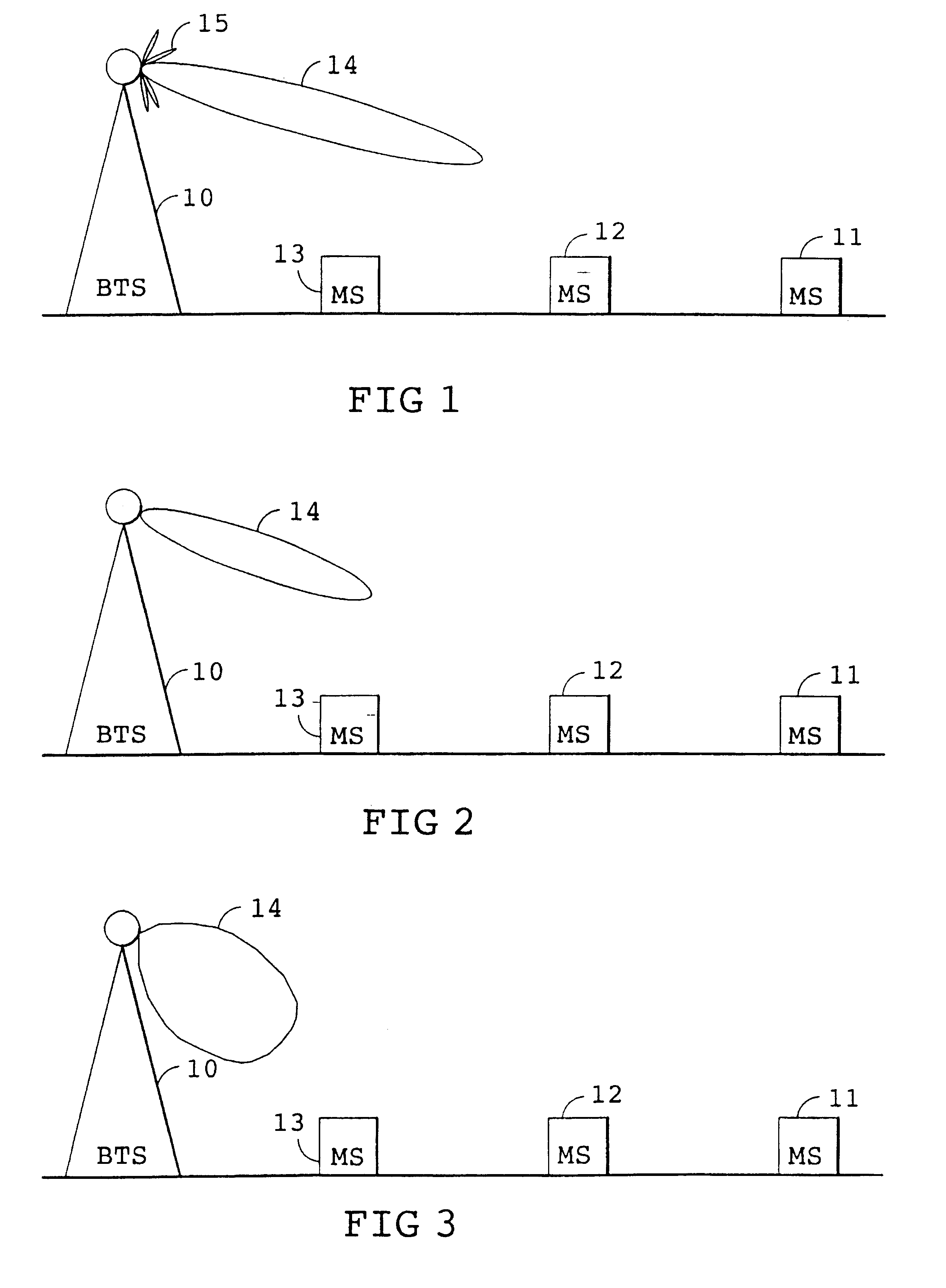
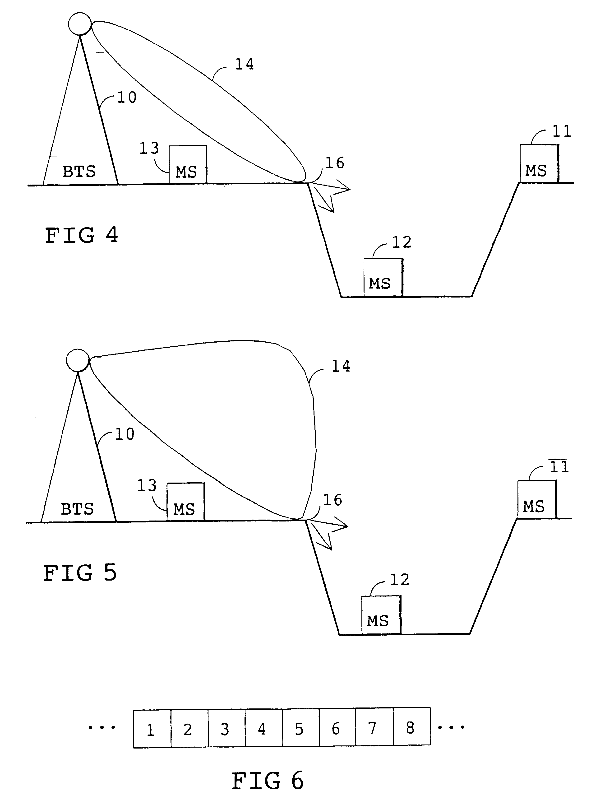
FIGS. 1 to 3 illustrate an inventive way of orienting an antenna, pattern in a cell of a cellular radio system. FIGS. 1 to 3 show a base station 10 and terminal equipments 11-13. The base station 10 has an antenna lobe 14 that can be oriented. In addition to the major lobe, the antenna lobe 14 comprises minor lobes 15, which are irrelevant to the invention. Hereinafter, the direction of the antenna lobe means the primary direction of the major lobe.

In FIG. 1 the base station 10 communicates with terminal equipment 11, which is preferably a mobile station. The antenna lobe of the base station 10 is oriented toward terminal equipment 11, which is here assumed to be located near...


PUM


Abstract

The invention relates to a method of optimizing coverage by changing the antenna pattern (14). In a solution of the invention, the base station (10) orients the antenna lobe (14) in the vertical direction toward a terminal equipment (11-13) by changing the shape of the antenna lobe according to a timing advance. The nearer the terminal equipment (11-13) is to the base station (10), the more downward the antenna lobe (14) is oriented by turning the antenna lobe (14) primarily downward or by changing the shape of the antenna pattern (14). In this way, transmission power, and thereby interference, is reduced.

Description

The invention relates to a method for optimising coverage, useful in a TDMA-based radio system which comprises several terminal equipments and base stations, and in which a signal is sent in time slots, a propagation delay of the signal between the terminal equipment and the base station is defined, and the antenna lobe of the base station is oriented.BACKGROUND OF INVENTIONAn example of a typical time divisional radio system is the GSM (Global System for Mobile communication). Multiple access is implemented by providing several carrier waves, each carrier wave having at most eight simultaneous users. In order that the signals of these eight users could be separated from one another, they are sent as bursts in predefined time slots. In other words, a transmitter transmits only at a predefined time instant. A frame comprises the time slots of eight users, and repetition of the frame allows transmission of even a large quantity of data.In prior art solutions, the coverage of a multipl...

Claims


Application Information

Patent Timeline
Patent Type & Authority Patents(United States)
IPC IPC(8): H01Q3/26H01Q3/30H04Q7/36H04B7/26H04W16/24H04W16/28
CPCH01Q3/26H04W16/28H01Q3/30H04W16/24
Inventor LEMPIAINEN, JUKKA
Owner HANGER SOLUTIONS LLC
Learn More