
Interleaver and method for interleaving an input data bit sequence using a coded storing of symbol and additional information

a technology of interleaving and input data, applied in the direction of coding, code conversion, digital transmission, etc., can solve the problems of increasing access time and memory requirements, insufficient memory location width, and insufficient address space of ram

Inactive Publication Date: 2006-10-24
TELEFON AB LM ERICSSON (PUBL)
View PDF19 Cites 39 Cited by
  • Summary
  • Abstract
  • Description
  • Claims
  • Application Information

AI Technical Summary

Benefits of technology

[0040]The invention in particular provides the major advantage, that the width of each memory location in a given storage means can be held small.
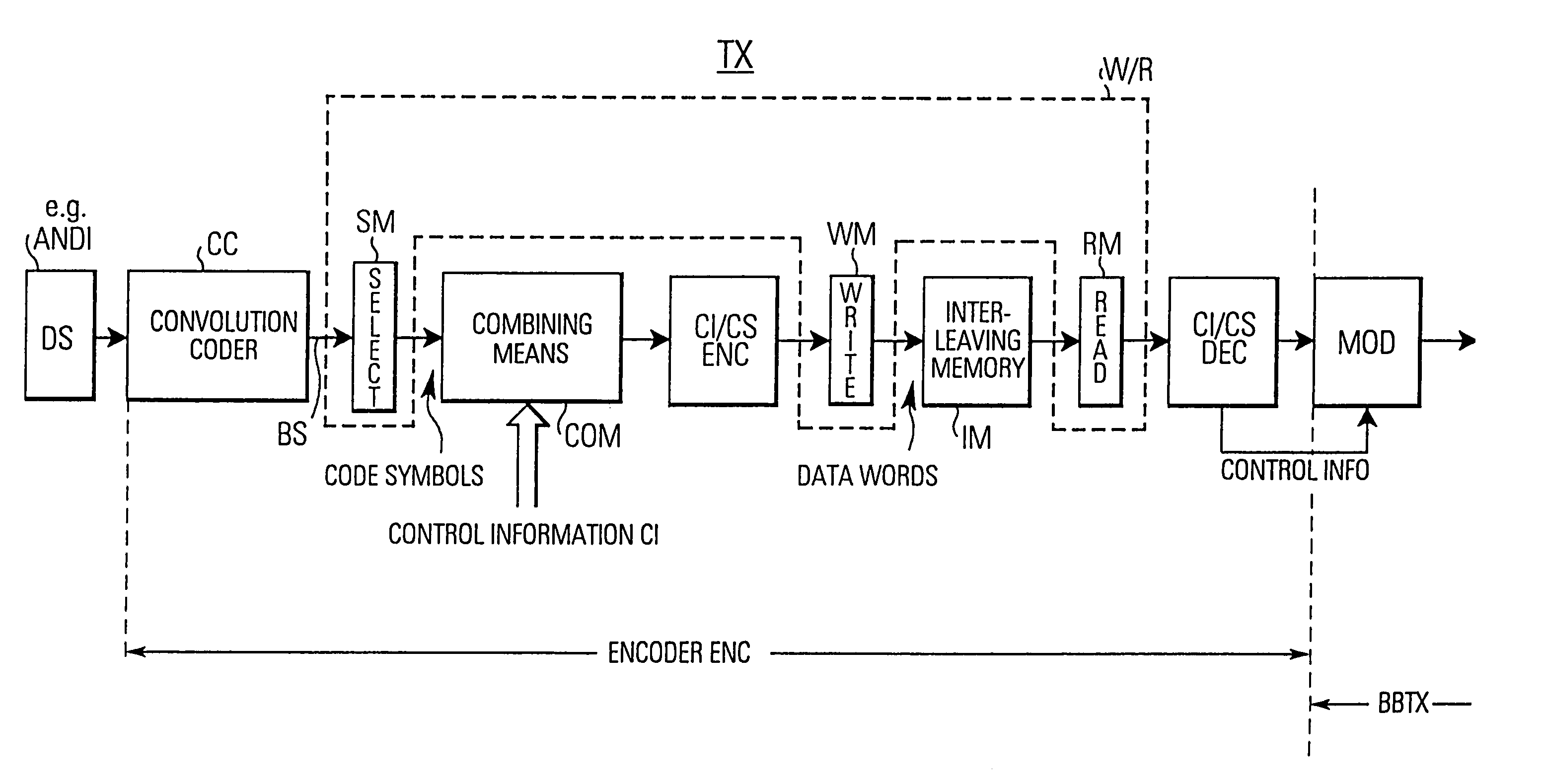
[0041]According to a first aspect of the invention, a combining means is used for combining the data bits of each code symbol with the associated control bits into a control information / code symbol data word. A control information / code symbol encoding means encodes this data word into a data word of less bits according to a predetermined encoding scheme. This encoded data word is then stored at memory locations of the memory used in the processing section. Therefore, instead of using more RAMs with bigger data width and less addressable memory space, the data symbols and the control information according to the invention will be encoded while using the available bit width. That is, by contrast to just storing control bits (e.g. four bits) together with one data symbol (e.g. two bits of one symbol) in one addressable memory location, the invention is based on the combining (encoding) of the data bits together with the control bits and the specific combinations (encoding) indicate a specific control function dedicated to the respective code symbol. Thus, a smaller bit width per memory location of the RAM can be used leading to relaxed memory requirements in the transmitter.
[0042]Having combined the data bits and the control bits and having encoded the combination into a data word of a smaller number of bits, a memory having a smaller number of bits per memory location can be used. This means that, using a memory of predetermined size, less bits have to provided per memory location and thus a larger address space is obtained.

Problems solved by technology

If the control information is quite large for each code symbol, then the width of a memory location may be insufficient (when a predetermined address space is needed), since each set of control bits must be stored together with its associated data bits (i.e. in form of code symbols).
In case that there is a great plurality of control bits the memory may not provide a sufficient number of bits per address such that additional read / write accesses must be performed which additionally increases the access time and the memory requirements.
In other words, if the width of the memory locations would be sufficient then the RAM may not have enough address space, i.e. not a sufficient number of addressable memory locations, to handle all the data of all user channels.

Method used


Image

  • Interleaver and method for interleaving an input data bit sequence using a coded storing of symbol and additional information
  • Interleaver and method for interleaving an input data bit sequence using a coded storing of symbol and additional information
  • Interleaver and method for interleaving an input data bit sequence using a coded storing of symbol and additional information

Examples


first embodiment

OF THE WRITE / READ MEANS

[0105]FIG. 12 shows an embodiment of the write / read means W / R used for selecting the data bits from the input bit sequence BS before they are combined, encoded and written as encoded data words to the interleaving matrix in the row direction and for reading out the encoded data words sequentially in the column direction to provide interleaved encoded data words which are then decoded into the data bits and the control bits to be provided to a modulation unit MOD generally shown in FIG. 6.

[0106]As shown in FIG. 12, the write / read means W / R comprises a shift register means SHR, a select means SM, a write means WM, a read means RD, a preload means PLD and a shift means SHFT. User data, i.e. the input data bit sequence BS, is input to the shift register means SHR.

[0107]It should be noted that the embodiment using a shift register means SHR and a select / write means SM / WM is only one embodiment of the invention in order to select the data bits from the input data bi...

second embodiment (

N=2 AND R=1 / 2)

[0113]Hereinafter, with reference to FIG. 13a, FIG. 14 an embodiment is described for forming code symbols consisting of two data bits, i.e. N=2 for an arbitrary (even) NW. It should be noted that this embodiment advantageously uses parallely output data bits from a convolutional encoder operating with a coding rate of r=1 / 2, however, it is also possible that the data bits arrive serially, in which case different timing relationships must be considered. However, the embodiment with several shift registers as shown in FIG. 13a and described hereinafter is not restricted to a combination with a particular convolutional encoder of r=1 / 2, since the number of (parallely) output data bits from the convolutional encoder is not directly linked to the number of data bits forming one code symbol. That is, the channel encoder performs a special channel encoding outputting a predetermined number of bits, whilst the modulation scheme (QPSK, 16QAM etc.) in the modulator determines h...


PUM


Abstract

The invention relates to a method for storing code symbols and additional control information in a processing means of an encoder of a communication system. In particular, the invention relates to the storing of code symbols together with additional control information in an interleaving memory (IM) of an interleaver. According to the invention, a combining means (COM) combines respective data bits (I, Q) forming a respective code symbol with their associated control bits into a control information / code symbol data word of a predetermined number (K) of bits. A control information / code symbol encoding means (CI / CS-ENC) encodes the control information / code symbol data words into encoded data words of a smaller number of bits. This data word with a smaller number of bits is then stored at a particular memory location in the interleaving memory (IM).

Description

FIELD OF THE INVENTION[0001]The invention relates to an interleaver for interleaving input data bit sequences of data bits of code symbols each consisting of a number of data bits together with additional information, in particular control information, consisting of a number of control bits which indicate control functions for each code symbol. The invention also relates to a method for interleaving such a data bit sequence. Furthermore, the invention relates to a transmitter where code symbols are processed together with control information.[0002]Thus, generally the invention relates to the processing of data symbols together with additional control information. Whilst the storage of the data information together with the control information is comparatively simple when only one user channel is considered, storage problems in the transmitter become quite severe when a great plurality of user channels (providing data information in terms of bits) are to be combined with control info...

Claims


Application Information

Patent Timeline
IPC IPC(8): H04L27/04H03M13/27
CPCH03M13/2707H03M13/2782H03M13/27
Inventor SONNING, RAIMUNDHUAMAN-BOLLO, GIAN
Owner TELEFON AB LM ERICSSON (PUBL)
Learn More