
Cooking appliance control system

a control system and cooking appliance technology, applied in the field of cooking appliances, can solve the problems of limiting the user to entering a single time, the process is not readily adapted to other food items, and the construction and internal programming of the cooking appliance has grown to be more complicated

Active Publication Date: 2006-10-24
MAYTAG
View PDF13 Cites 90 Cited by
  • Summary
  • Abstract
  • Description
  • Claims
  • Application Information

AI Technical Summary

Benefits of technology

"The present invention is a control system for a cooking appliance that allows consumers to cook food with minimal effort. It allows for quick start cooking with just two input parameters, and also allows for a cold start mode for faster cooking. The control system can be programmed through a control panel based on recipes or other cooking instructions. The invention provides a special feature button that signals the control system to automatically start the cooking process after a cook time is inputted. The control system also allows consumers to input both minimum and maximum cook times for the cooking operation. The technical effects of the invention are improved efficiency and convenience for consumers, as well as improved cooking performance and control over the cooking process."

Problems solved by technology

All in all, the construction and internal programming of the cooking appliance has grown to be more complicated.
While being simple, the process does not readily lend itself to other food items, such as baked goods and the like.
In addition, if a consumer desires to set a cook duration, he / she is limited to entering a single time.
At that point, the food item is left in the oven for an additional time period which, if the timer is not set again or if the consumer simply looses track of the time, could lead to the food item becoming overcooked or even burned.

Method used


Image

  • Cooking appliance control system
  • Cooking appliance control system
  • Cooking appliance control system

Examples


Embodiment Construction

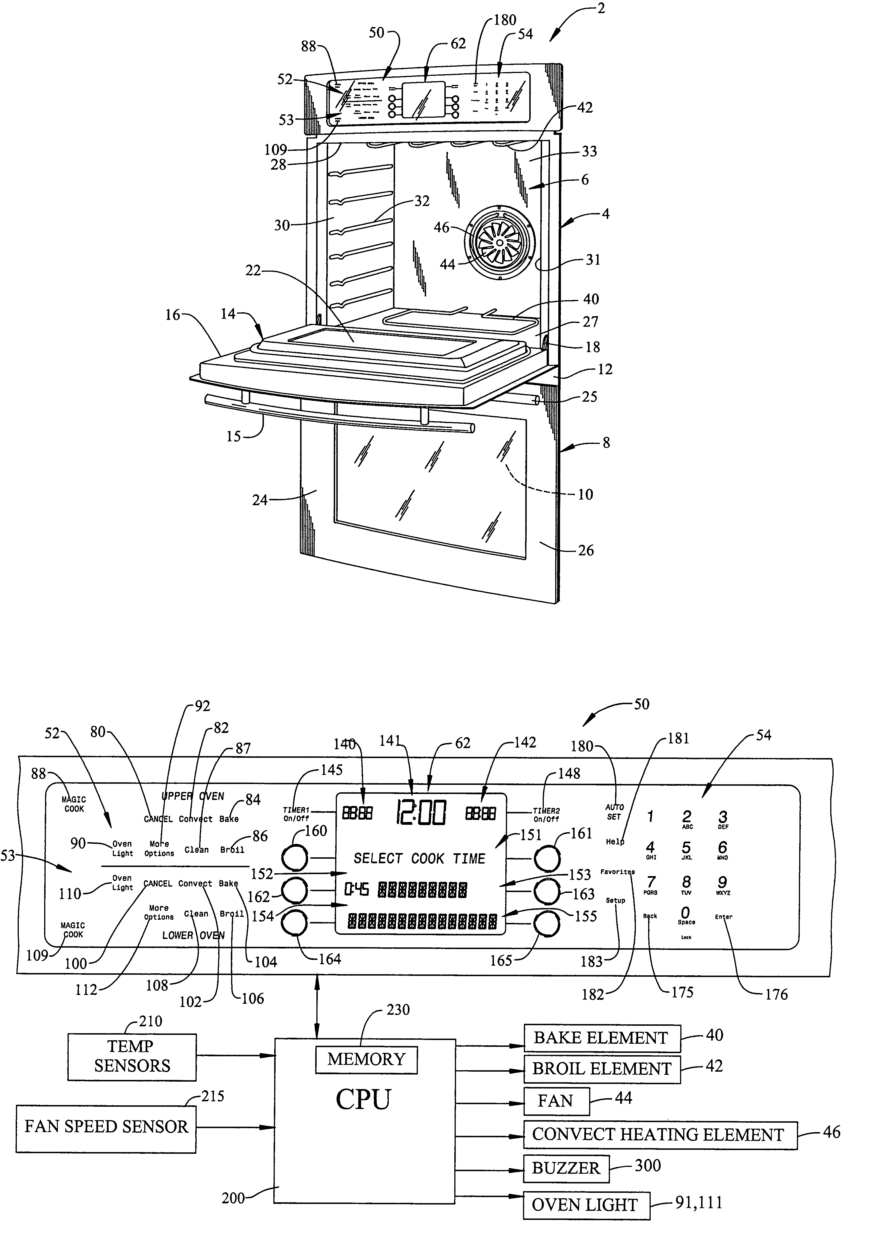
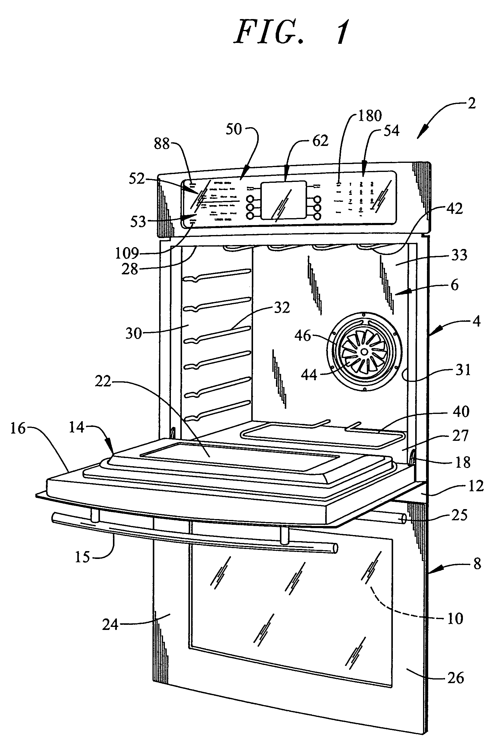
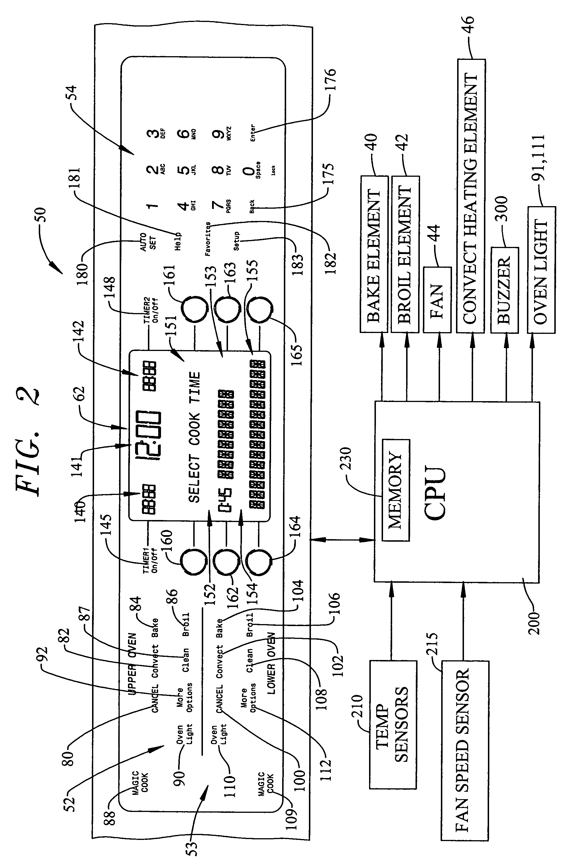
[0016]With initial reference to FIG. 1, a cooking appliance constructed in accordance with the present invention is generally indicated at 2. Cooking appliance 2, as depicted, constitutes a double wall oven. However, it should be understood that the present invention not limited to this model type and can be incorporated into various types of oven configurations, e.g., cabinet mounted ovens, as well as both slide-in and free standing ranges. In any event, in the embodiment shown, cooking appliance 2 constitutes a dual oven wall unit including an upper oven 4 having upper oven cavity 6 and a lower oven 8 having a lower oven cavity 10. Cooking appliance 2 includes an outer frame 12 for supporting, at least in part, both upper and lower oven cavities 6 and 10.

[0017]In a manner known in the art, cooking appliance 2 is equipped with a door assembly 14 to selectively provide access to upper oven cavity 6. As shown, door assembly 14 includes a handle 15 at an upper portion 16 thereof. Door...


PUM


Abstract

A control system for a cooking appliance enables a consumer to selectively program a cooking appliance through a control panel in a conventional mode based on established cooking times and temperatures, as well as in a simplified mode incorporating a minimal number of programming steps. In the simplified mode, the consumer selects a first, non-temperature related special features button and inputs a cook time. Immediately following input of the cook time, the control system starts a cooking operation. If the selected time is greater than a predetermined value, the control system automatically operates the cooking appliance in a cold start mode. An override is provided to disable the cold start mode if so desired. In addition, the control system allows a consumer to input both minimum and maximum cook times for the cooking operation.

Description

BACKGROUND OF THE INVENTION[0001]1. Field of the Invention[0002]The present invention pertains to the art of cooking appliances and, more particularly, to a cooking appliance including a control system having a simplified programming algorithm for initiating a cooking operation.[0003]2. Discussion of the Prior Art[0004]Over the years, there have been many advances in the art of cooking appliances. Various heat sources, such as convection air, microwave and IR heating elements have been used, in one way or another, to perform a cooking operation. Mechanical components such as switches, thermostats and other controls have been replaced, or at least supplemented, by electronic control systems. Rotary knobs are slowly giving way to touch pads and touch screen displays. Many new features have been added to the cooking appliance, such as preprogrammed operations, recipes, and multi-stage cooking operations. Many appliances include a help screen that aides a consumer in navigating through ...

Claims


Application Information

Patent Timeline
Patent Type & Authority Patents(United States)
IPC IPC(8): H05B1/02A21B1/40F27D19/00
CPCF24C7/082
Inventor HORTON, WILLARD HENRYSAUTER, KENNETH E.STERCHI, MARILYN L.
Owner MAYTAG
Learn More