
Removable heater for a hot runner nozzle

a heater and nozzle technology, applied in the field of injection molding apparatus, can solve the problems of reducing the efficiency of difficult to achieve efficient heat the difficulty of achieving efficient heat transfer between the heater and the nozzle, etc., to achieve efficient heat transfer, easy installation and removal, and maximum surface contact

Inactive Publication Date: 2006-10-24
MOLD MASTERS 2007
View PDF32 Cites 3 Cited by
  • Summary
  • Abstract
  • Description
  • Claims
  • Application Information

AI Technical Summary

Benefits of technology

[0053]threading the heater assembly onto the injection nozzle and generating a clamping force between the heater assembly and the injection nozzle to maximize the surface contact between the heater assembly and injection nozzle.
[0054]The present invention provides advantages in that the heater assembly is relatively easy to install and remove while the injection nozzle is in communication with the manifold. In addition, the contact between the threaded heater sleeve and the threaded nozzle body enables efficient heat transfer to occur. Furthermore, the clamping force between the heater assembly and the nozzle, or manifold, is maintained regardless of the temperature of the heater assembly.

Problems solved by technology

Integrated electrical heaters are more expensive to manufacture and typically cannot be replaced without replacing the entire nozzle.
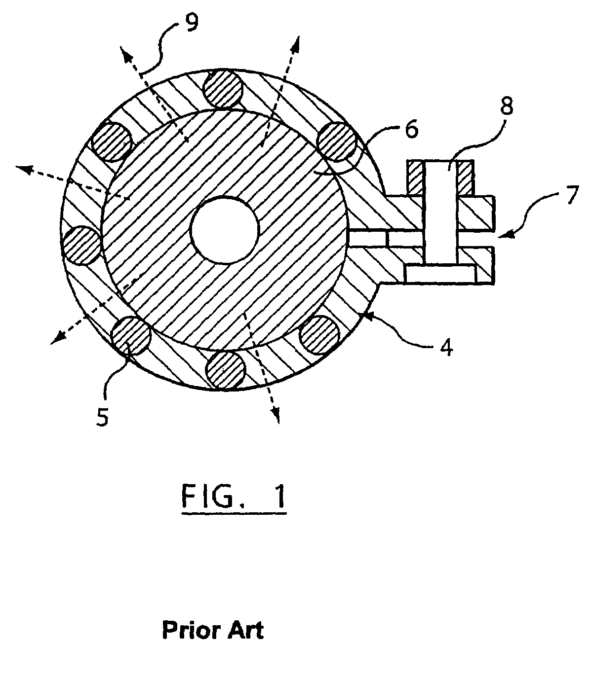
A disadvantage of the known removable heaters in injection molding is that achieving efficient heat transfer between the heater and the nozzle can be difficult.
Because the heater is a separate component, gaps can occur between the heater and the nozzle or manifold, any gap between these components reduces the efficiency of the heat transfer.
A further disadvantage of known removable heaters is that they often require additional space to accommodate a locking mechanism.
This is a problem in high cavitation molding applications where the space between the adjacent nozzle is minimized.
Achieving full contact between smooth heater surfaces and smooth nozzle or manifold body surfaces having different expansion coefficients is a difficult task particularly when the temperature of the heater cycles between hot and cold temperatures.
As a result, the clamping heater devices of the prior art tend to be complex and thermally less efficient than expected.
In addition, some skill and additional time is typically required to properly install the prior art devices.

Method used


Image

  • Removable heater for a hot runner nozzle
  • Removable heater for a hot runner nozzle
  • Removable heater for a hot runner nozzle

Examples


Embodiment Construction

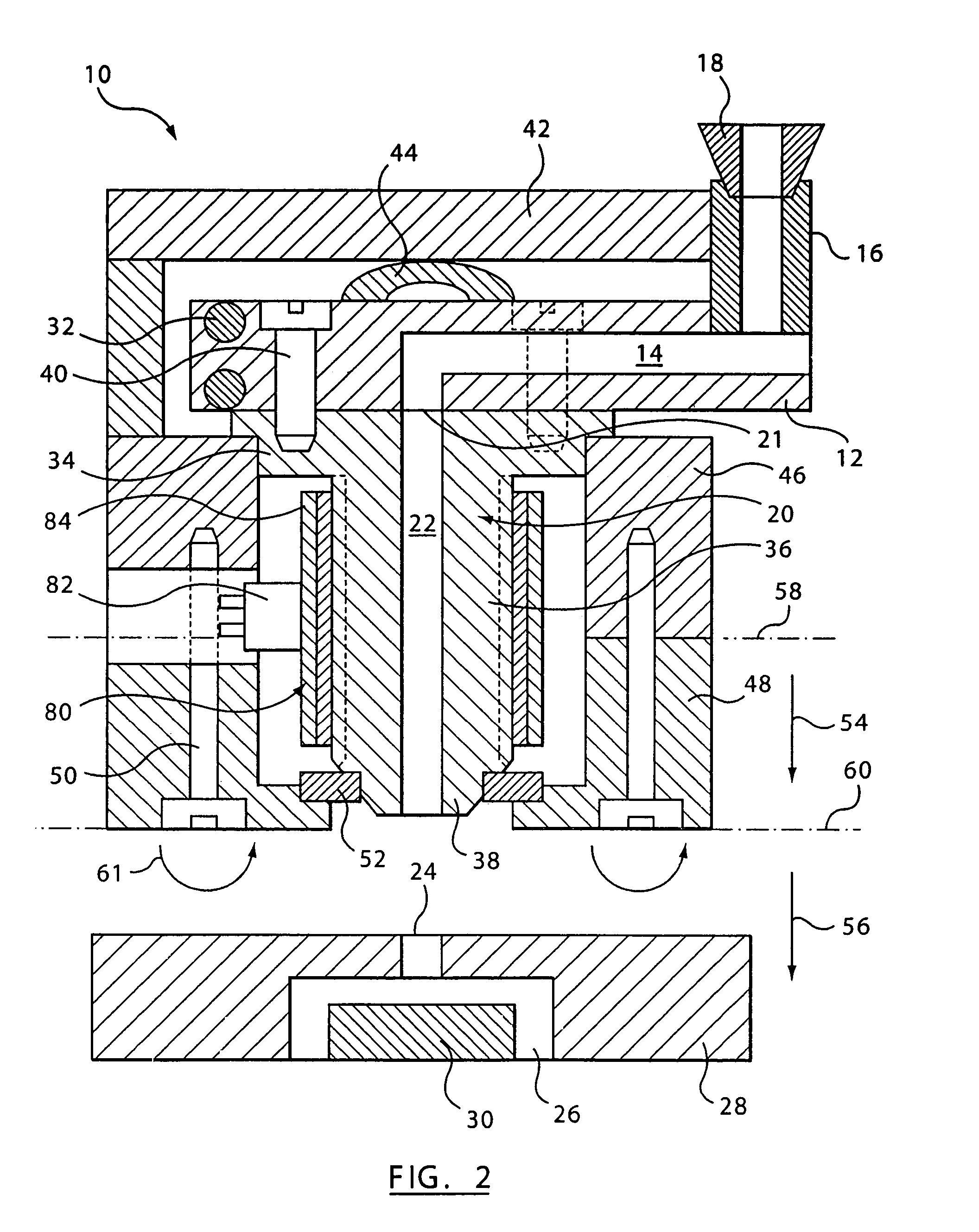
[0079]Referring now to FIG. 2, an injection molding apparatus according to an embodiment of the present invention is generally shown at 10. The injection molding apparatus 10 comprises a manifold 12 having a manifold melt channel 14 for receiving a melt stream of moldable material under pressure from a manifold bushing 16. The manifold bushing 16 extends between a backing plate 42 and the manifold 12 and is in communication with a machine nozzle 18. A spacer 44 is provided between the backing plate 42 and the manifold 12. The spacer 44 is typically flexible in order to compensate for heat expansion of the injection molding apparatus 10.

[0080]A hot runner nozzle 20 is coupled to an outlet 21 of the manifold 12. A nozzle channel 22 extends through each nozzle 20 for receiving the melt stream of moldable material from the manifold 12. A mold gate 24 is located adjacent the tip of each nozzle 20. The flow of moldable material through the mold gate 24 is controlled to allow delivery of t...


PUM

PropertyMeasurementUnit
pressureaaaaaaaaaa
forceaaaaaaaaaa
temperatureaaaaaaaaaa

Abstract

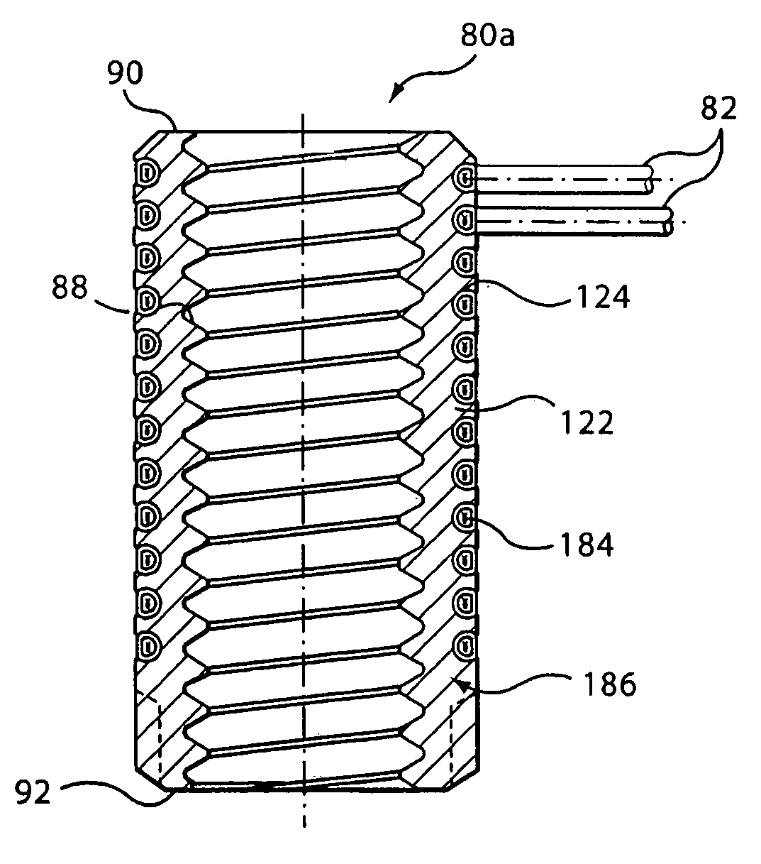
A heater assembly for an injection molding apparatus comprises a heater sleeve having a threaded inner surface for engaging a threaded outer surface of a nozzle body of a nozzle or a threaded surface of a mold manifold. A clamping element such as a lock nut or a spring is provided adjacent the heater sleeve. The lock nut and / or the spring abuts the heater sleeve to force the threaded inner surface of the heater sleeve into contact with the threaded outer surface of the nozzle body. This removable clamped heater assembly operates regardless of the temperature of heater.

Description

CROSS REFERENCE TO RELATED APPLICATIONS[0001]This application is a continuation of U.S. application Ser. No. 10 / 2 10,883, filed Aug. 2, 2002 now U.S. Pat. No. 6,780,003.FIELD OF THE INVENTION[0002]The present invention relates generally to an injection molding apparatus and in particular to a removable heater for injection nozzles and manifolds.BACKGROUND OF THE INVENTION[0003]Heat generation and management of molten material in an injection molding apparatus is important for ensuring the production of high quality molded parts. Heating of the molten material is typically accomplished by locating several electrically powered heaters adjacent to the flow channel of the machine nozzle, the mold manifold and the hot runner nozzle. Several different types of electrical heaters are available including coil heaters, band heaters, film heaters, heat pipes, induction heaters and cartridge heaters. The heaters are sometimes integrated or embedded into the nozzle housing in order to optimize ...

Claims


Application Information

Patent Timeline
Patent Type & Authority Patents(United States)
IPC IPC(8): B29C45/20B29C45/27H05B3/42H05B3/46
CPCB29C45/2737H05B3/42H05B3/46B29C2045/2743B29C2045/2772
Inventor SICILIA, ROBERTBABIN, DENISGUENTHER, HANS
Owner MOLD MASTERS 2007
Learn More