
Outside rearview mirror flexing mechanism and control method thereof

a technology of rearview mirror and flexing mechanism, which is applied in the direction of mirrors, instruments, mountings, etc., can solve the problem that devices are not capable of detecting

Inactive Publication Date: 2006-10-24
FICO MIRRORS SA
View PDF8 Cites 4 Cited by
  • Summary
  • Abstract
  • Description
  • Claims
  • Application Information

AI Technical Summary

Benefits of technology

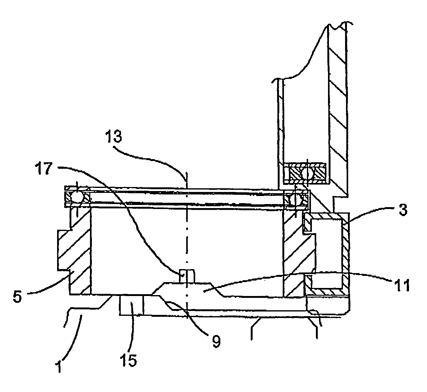
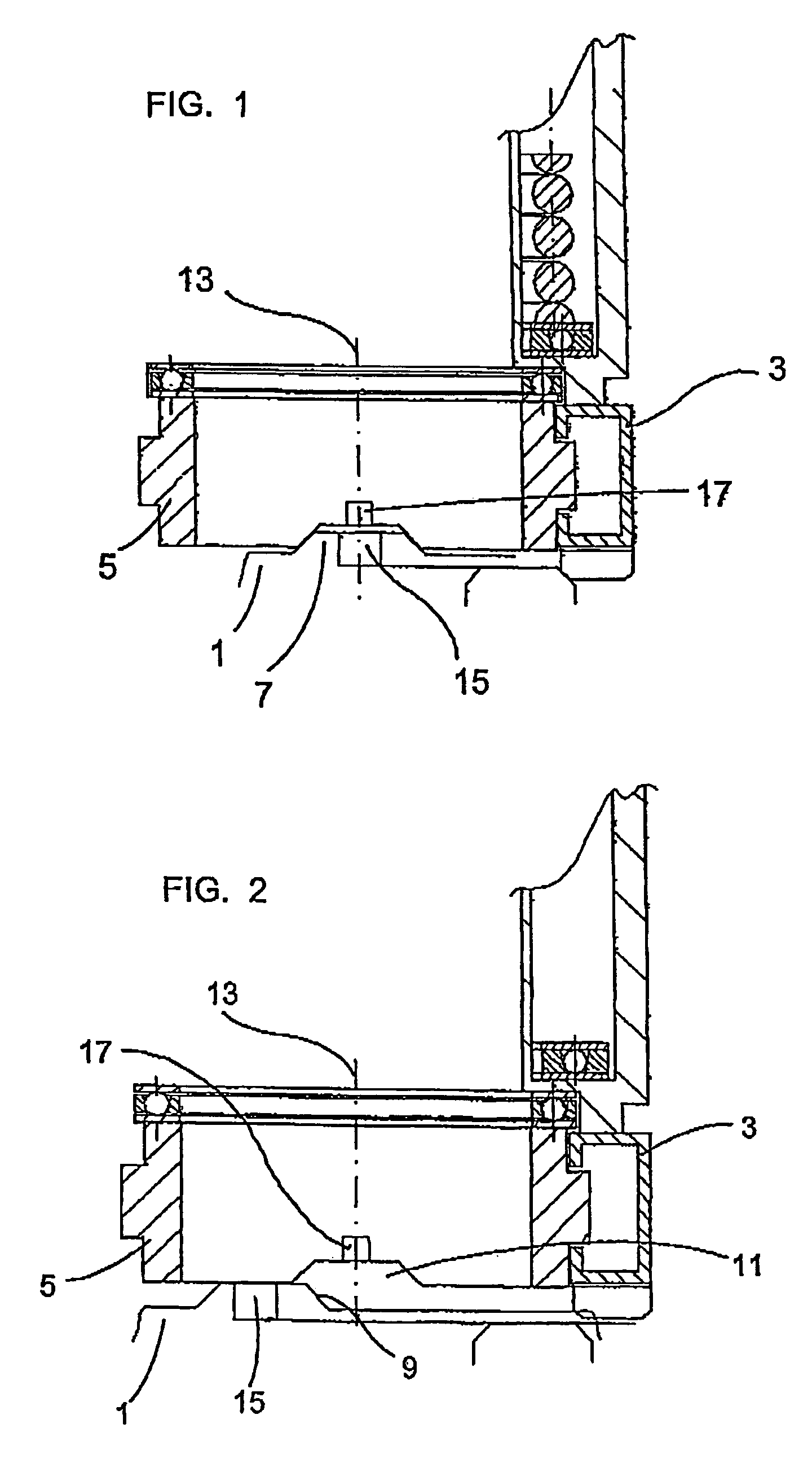
[0013]It is possible to provide the position detector with a plurality of Hall effect sensors and a plurality of magnets, however, it may be sufficient and logically advantageous, to provide one Hall effect sensor and one magnet on each of the meshing points where the meshing point carrying the Hall effect sensor can mesh. Furthermore, the magnet may be any type, such as for example an electromagnet. However, it is particularly advantageous to use a permanent magnet, which simplifies the construction of the ensemble.
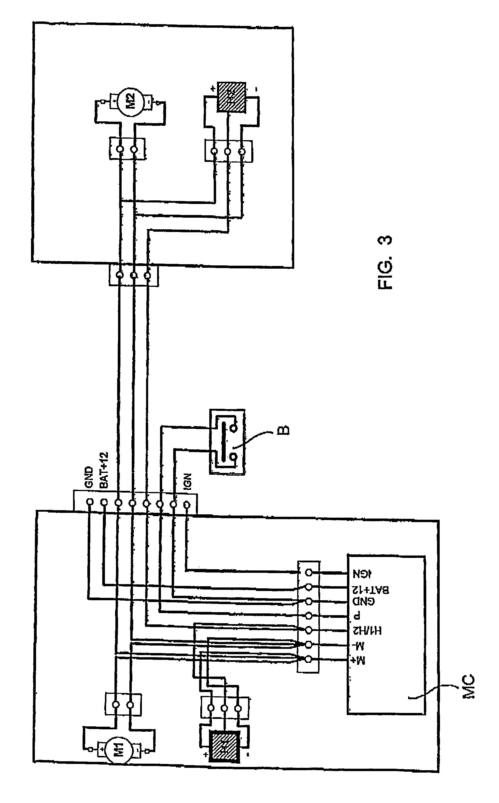
[0014]Another additional advantage can be achieved by causing the Hall effect sensor-to be supplied by the two electrical conduits supplying the electric motor. In this way, the amount of additional electrical conduits is reduced to a minimum, with the subsequent savings in costs and space. A preferred embodiment in this sense consists in supplying the sensor on the basis of electrical impulses having a duration short enough to prevent them from moving the corresponding electric motor but long enough to obtain a reading of the sensor output signal. In this way, the sensor is activated only during a brief period of time, during which the sensor output signal is read, and it remains inactivated until a new sensor reading is required. For example, a mechanism in which the reading of the sensor output signal is taken every 0.5–3 s (preferably every 1.3 s), and where the electrical impulse lasts approximately 1–1.5 ms (preferably 1.2 ms).
[0016]Flexing mechanisms usually include elements that require electrical power (electric motor, electronic control circuit, position detector, etc.). The source of electrical power is preferably the vehicle battery. Advantageously, the flexing mechanism is capable of attaining an activated state directly with the vehicle ignition key, so that when turning said key in the ignition direction corresponding to said engine, which in general usually includes a contact step with the battery and, subsequently, a start-up motor activation step, said outside rearview mirror is moved from said flexed position to said extended position and upon turning said key in the direction for switching off said motor said outside rearview mirror is moved from said extended position to said flexed position. In this way, the rearview mirror is positioned (between the flexed and extended positions) automatically, without the need for any particular action to be taken by the driver.
[0017]In order to prevent the electric motor from trying to move the rearview mirror or the flexing mechanism to an inaccessible position, in the sense that there is some physical obstacle preventing the desired position from being reached, it is convenient that the electronic control circuit in the flexing mechanism detects the electric current ramp circulating through the electric motor when it tries to move the rearview mirror but is unable to do so, either because the rearview mirror has reached one of said flexed or extended positions or because there is an obstacle in its path blocking its movement. In this way, the flexed and extended positions of the rearview mirror can be defined by simple mechanical stops and, at the same time, it is possible to prevent any external obstacle from jeopardising the integrity of the motor. Moreover, if the external obstacle is, for example, the driver's finger, or someone else's, they are protected from injuring themselves. Advantageously in these cases, the electronic control circuit interrupts the electric current supply to the motor according to the values of said current intensity ramp and some threshold values that are a function of the room temperature and the battery voltage. In this way, the current intensity fluctuations that must be considered as the result of the variation in room temperature are taken into account and, as well as therefore the variation in the temperature of the flexing mechanism components.
[0019]Preferably another embodiment of the invention is obtained when the electronic control circuit measures the time taken to perform a movement and compares it with a minimum target time in order to assess whether said movement has made it possible to reach said target position. In this way, the electronic control circuit can determine whether the position reached is the correct one or not.
[0025]Preferably the flexing mechanism comprises a microcontroller, since in this way the various functions can be carried out more efficiently.

Problems solved by technology

However, these devices are not capable of detecting whether the flexing mechanism is in the locked or unlocked or disengaged position, and therefore it is necessary that the user revises the system manually.

Method used


Image

  • Outside rearview mirror flexing mechanism and control method thereof
  • Outside rearview mirror flexing mechanism and control method thereof
  • Outside rearview mirror flexing mechanism and control method thereof

Examples


Embodiment Construction

[0031]The flexing mechanism disclosed is very similar, in mechanical terms, to those described in document ES P9902630 or in document EP 748.719 A2, published on 18. Dec. 1996, hereby incorporated herein by reference, and which form part of the state of the art known to a person skilled in the art. Therefore the common mechanical contents with mechanisms described in said documents shall not be explained.

[0032]With respect to this invention, it is simply to be remembered that the flexing mechanism has a support chassis 1, integral with the vehicle, a housing chassis 3, which is integral with the rearview mirror, and a crown gear 5, forming the union between support chassis 1 and housing chassis 3.

[0033]Support chassis 1 has gear teeth 7, with inclined side walls 9 that are capable of meshing in recesses 11 on crown gear 5. Housing chassis 3 is joined to crown gear 5 so that it can rotate around a rotation axis 13. To this end it is provided with an electric motor that acts upon a wo...


PUM


Abstract

An outside rearview mirror flexing mechanism, which is capable of moving the outside rearview mirror between a flexed position and an extended position and vice versa, and which is of the type comprising an electric motor, a mechanical transmission and an electronic control circuit. The flexing mechanism is capable of attaining an activated state by being connected to an electrical power source, and it is capable of being in a locked position and in an unlocked position. The flexing mechanism is provided with a position detector which is capable of detecting the locked position and the unlocked position.

Description

DESCRIPTION[0001]The invention relates to a flexing mechanism of an outside rearview mirror of an automobile vehicle, capable of moving said outside rearview mirror between a flexed position and an extended position and vice versa, of the type comprising an electric motor, a mechanical transmission and an electronic control circuit, where said flexing mechanism can attain an activated state by being connected to an electrical power source, where said flexing mechanism can be in a locked position and in an unlocked or disengaged position. These flexing mechanisms can be automatic and can be controlled from inside the vehicle.[0002]The invention also relates to a method of controlling said flexing mechanism.BACKGROUND OF THE INVENTION[0003]The rearview mirror flexing mechanisms of the type indicated above are known. For example, the mechanisms described in document ES-A-2 166 677 or in document EP-A-748719, published on 18. Dec. 1996, hereby incorporated herein by reference, represent...

Claims


Application Information

Patent Timeline
IPC IPC(8): B60R1/074
CPCB60R1/074B60R1/076
Inventor LUNA, FRANCESC DAURAVERA, ORIOL ROVIRASERAPIO, LLORENC SERVERA
Owner FICO MIRRORS SA
Learn More