Eureka AIR delivers breakthrough ideas for toughest innovation challenges, trusted by R&D personnel around the world.

Spring powered toggle joint lock for a folding knife

a toggle joint and folding knife technology, applied in the direction of thrusting weapons, white arms/cold weapons, weapons, etc., can solve the problems of inability to meet the needs of two hands, inability to manipulate the opening and closing of the blade, and inability to meet the needs of shortcoming

Inactive Publication Date: 2006-10-24
HAWK GRANT WOODROW
View PDF19 Cites 25 Cited by
  • Summary
  • Abstract
  • Description
  • Claims
  • Application Information

AI Technical Summary

Benefits of technology

[0023]In accordance with the present invention, a spring powered, toggle joint, lock for a folding knife. Such knife configured with a spring so as to propel the closing blade towards closed and the opening blade towards open. A cam shaped rear toggle inducing

Problems solved by technology

Typical, in that, all examples known to this applicant share a common disadvantage.
That disadvantage is the necessity of using two hands to manipulate the opening and closing of the blade.
This is a short coming unacceptable in today's market place.

Method used


Image

  • Spring powered toggle joint lock for a folding knife
  • Spring powered toggle joint lock for a folding knife
  • Spring powered toggle joint lock for a folding knife

Examples


Embodiment Construction

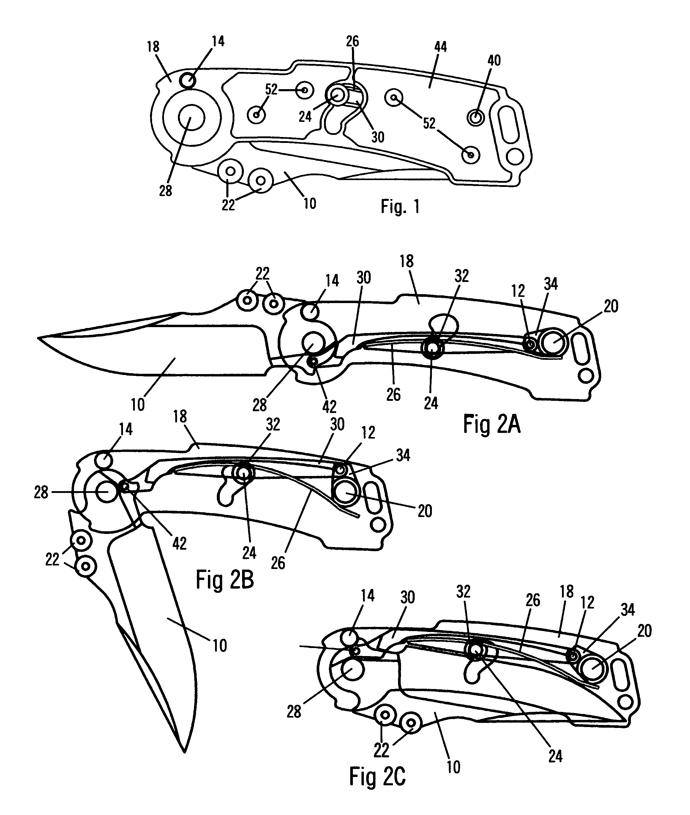
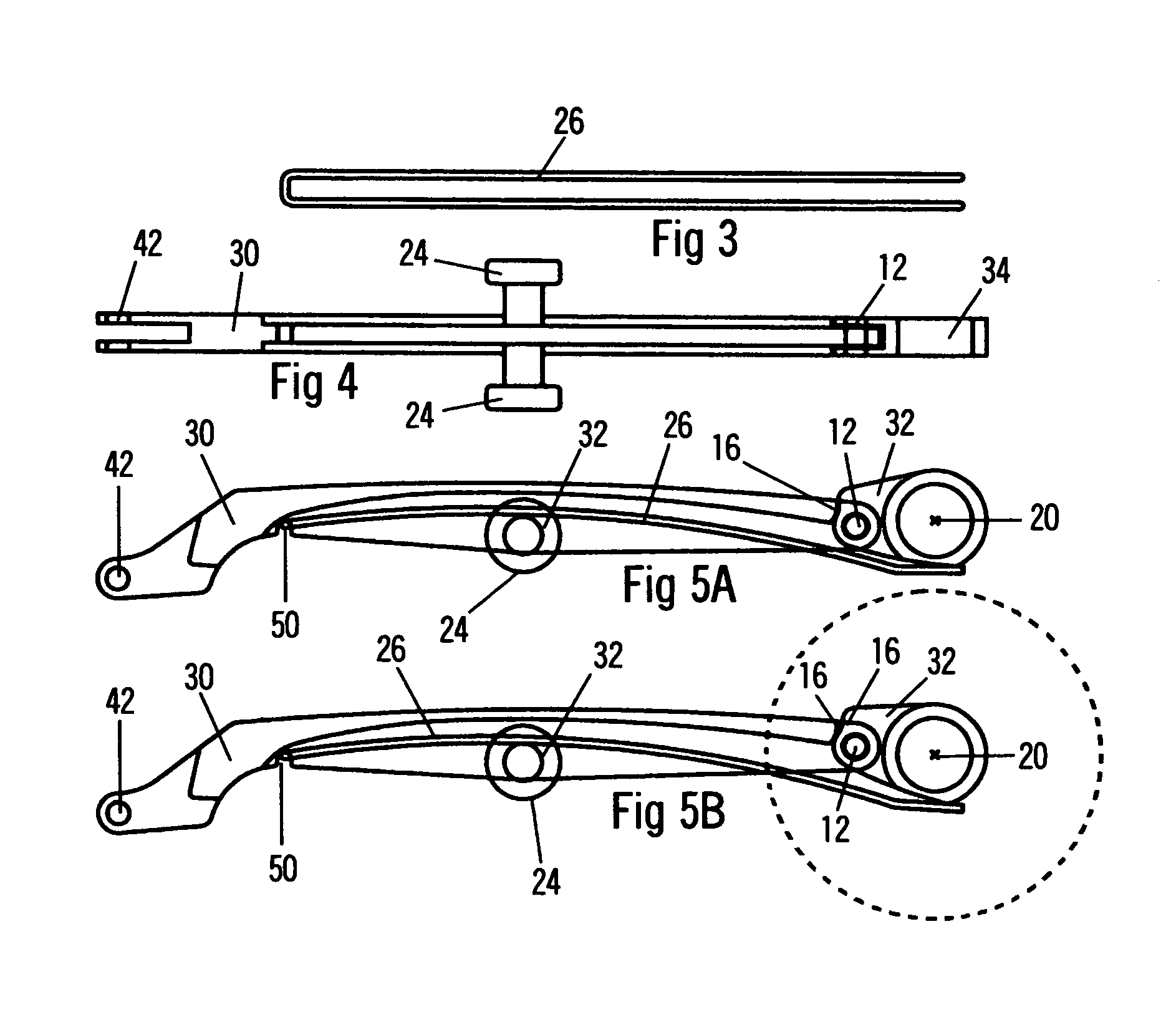
[0024]A typical embodiment of the “spring powered toggle joint lock” of the present invention is shown at the figures listed below. FIG. 1 shows a plan view of a completely assembled folding knife in the closed position. FIG. 2C shows the same knife in the same closed position but cutaway to reveal the internal components. In FIG. 2C the traveling toggle 30 is pinned to the blade 10 at the traveling toggle to blade, pivot point 42 at its forward end and pinned to the rotating toggle 34 at the toggle knee joint pivot point 12 at its rearward end. The knife of FIG. 2C is held closed by the spring 26 which is more clearly defined in FIGS. 3 through 5B. FIG. 2B shows the knife opened to its halfway point which represents the maximum loading of spring 26. FIG. 2A shows the knife in its fully opened and locked position at which point the toggle knee joint pivot point 12 comes to rest slightly beyond an imaginary straight line drawn between the center of rotation of the rotating toggle 20 ...


PUM


Abstract

A “spring powered toggle joint lock” for a folding knife; comprising a blade lock of three primary elements. A rotating toggle link at the rear of the knife handle connected by a pivoting knee joint to a traveling toggle, which is in turn pivotally joined to the tang of the opening and closing blade. A spring configured so as to constantly urge the pivot points of the rotating toggle and traveling toggle into a straight line, generating an over-center action. The effect of the spring and toggle combination is to propel the opening blade towards open and the closing blade towards closed. Control pins attached to the traveling toggle and protruding to the surface of the handle, on both sides of the handle, provides the means to collapse the toggle lockup by thumb pressure, thereby allowing ambidextrous, one handed manipulation of a toggle locking folding knife.

Description

CROSS-REFERENCE TO RELATED APPLICATIONS[0001]This application claims the benefit of provisional patent application Ser. No. 60 / 503 / 663, filed Sep. 19, 2003 by the present inventor.FEDERALLY SPONSERED RESEARCH [0002]Not ApplicableSEQUENCE LISTING OR PROGRAM [0003]Not ApplicableBACKGROUND OF THE INVENTION [0004]1. Field of Invention[0005]This invention relates to a toggle joint, locking mechanism for a folding knife and more specifically to a spring powered, toggle joint, lock that allows for one handed opening and closing of a toggle joint, locking folding knife.[0006]Although the toggle lock method of locking a folding knife is known to provide a very positive and safe lock up, designs of the past suffer disadvantages. Old designs requiring the use of both hands are no longer in favor to most consumers who insist on easy, one handed manipulation of a folding knife. What is needed is a spring powered toggle joint locking mechanism that overcomes these disadvantages.[0007]2. Prior Art...

Claims


Application Information

Patent Timeline
IPC IPC(8): B26B1/10B26B1/04
CPCB26B1/048
Inventor HAWK, GRANT WOODROW
Owner HAWK GRANT WOODROW
Why Eureka
Eureka Blog
Learn More