Indicator system having multiple LEDs
a technology of indicator system and led, which is applied in the direction of identification means, instruments, lighting support devices, etc., can solve the problem that the effect of less likely to be achieved in the control of the flashing switch
- Summary
- Abstract
- Description
- Claims
- Application Information
AI Technical Summary
Benefits of technology
Problems solved by technology
Method used
Image
Examples
first embodiment
[0029][First Embodiment]
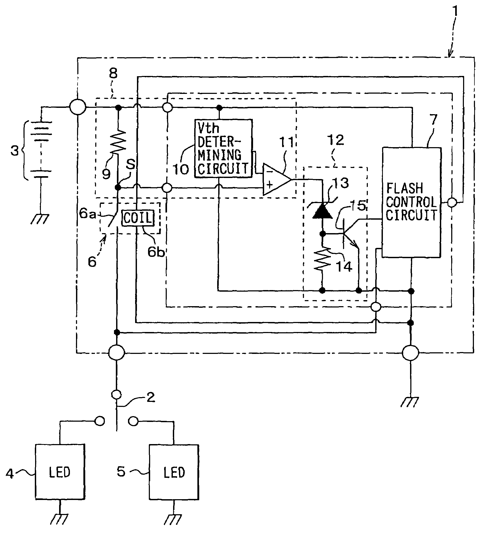
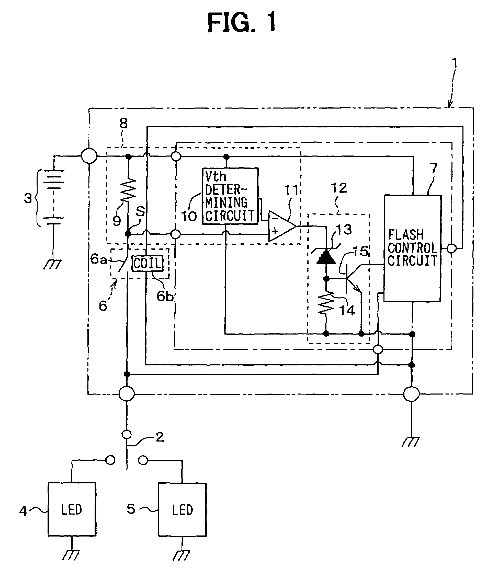
[0030]Referring to FIG. 1, an indicator system includes an indicator control unit 1, an indicator switch 2, a battery 3, a left LED indicator 4, and a right LED indicator 5. The indicator control unit 1 controls illumination of the left indicator 4 and the right indicator 5. It turns on the left indicator 4 or the right indicator 5, whichever selected by a driver through operation of the indicator switch 2 and supplied with power from the battery 3. The indicator switch 2 is arranged behind a steering wheel inside a vehicle.
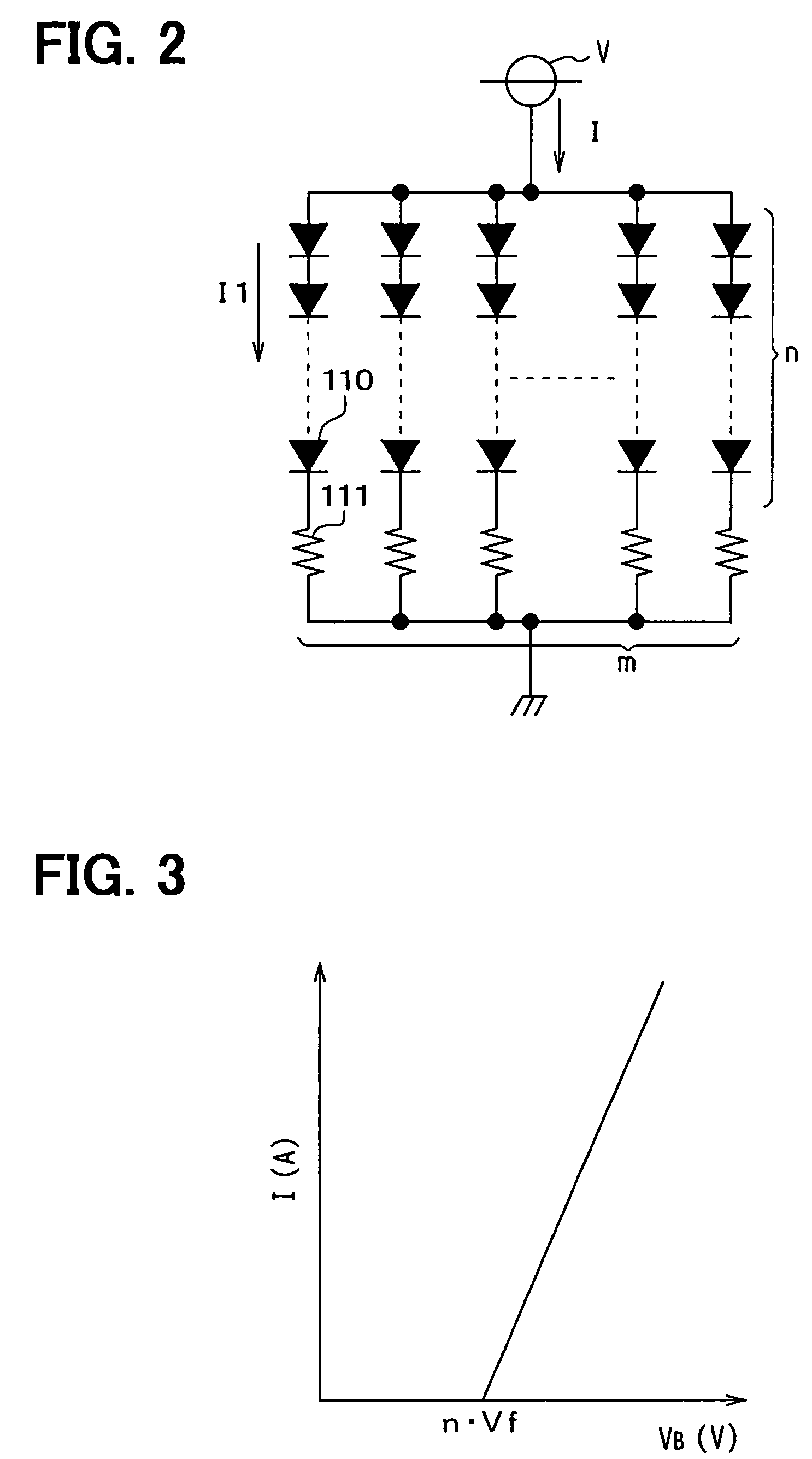
[0031]Each indicator 4, 5 is constructed of multiple LEDs 110 and resistors as shown in FIG. 2. An n number of LEDs 110 and a resistor 111 are connected in series. This series circuit is referred to as an LED line. An m number of LED lines are connected in parallel with each other. The indicator 4, 5 flashes when power is supplied from the battery 3 to each LED line via the indicator control unit 1 and the indicator switch 2. Although only...
second embodiment
[0053][Second Embodiment]
[0054]Referring to FIG. 5, an indicator control unit 20 has a similar configuration to that of the first embodiment. The low-voltage filtering circuit 12 is not included in this indicator control unit 20. Moreover, a threshold voltage determining circuit 21 is included instead of the threshold voltage determining circuit 10. Other components and circuits are the same as those in the first embodiment. Therefore, they will not be discussed in this second embodiment section.
[0055]The threshold determining circuit 21 shown in FIG. 6 is connected between the battery 3 and the ground. It includes the first, the second, the third and the fourth resistors R1, R2, R3, R4, and the first and the second zener diode ZD1, ZD2. The first resistor R1, the first zener diode ZD1, the second resistor R2, and the second zener diode ZD2 are connected in series in this order from the battery 3. The third resistor R3 and the fourth resistor R4 are connected in series and they are ...
third embodiment
[0065][Third Embodiment]
[0066]Referring to FIGS. 8, 9, the threshold determining circuit 31 includes a constant current source 31a, the first through the fifth resistors R11–R15, and an NPN bipolar transistor T1. The first resistor R11 is connected in series with the battery 3 and with the ground. The constant current source 31a and the resistor R11 form a constant voltage section. A voltage at a point between the constant current source 10a and the first resistor R11, namely, a constant voltage developed by the constant current flowing through the resistor R11, is applied to the base of the transistor T1.
[0067]The second resistor R12 is connected between the base and the emitter of the transistor T1. The third and the fourth resistors R13, R14 are connected in series between the collector of the transistor T1 and the battery 3. The fifth resistor R15 is connected between the emitter and the ground. The voltage drop at the third resistor R13, which is measured at a point between the...
PUM
 Abstract
Description
Claims
Application Information
 - R&D
- Intellectual Property
- Life Sciences
- Materials
- Tech Scout
- Unparalleled Data Quality
- Higher Quality Content
- 60% Fewer Hallucinations
Browse by: Latest US Patents, China's latest patents, Technical Efficacy Thesaurus, Application Domain, Technology Topic, Popular Technical Reports.
© 2025 PatSnap. All rights reserved.Legal|Privacy policy|Modern Slavery Act Transparency Statement|Sitemap|About US| Contact US: help@patsnap.com


