
Automated elevational adjustment of passenger loading bridge

a technology for loading bridges and passenger vehicles, applied in the direction of bridges, launching weapons, transportation and packaging, etc., can solve the problems of slow bridge movement based on bridge movement, time-consuming image processing, manual height adjustment of operator's final height adjustment, etc., to achieve accurate and fast response to final height adjustment

Inactive Publication Date: 2006-10-17
AMERIBRIDGE
View PDF11 Cites 9 Cited by
  • Summary
  • Abstract
  • Description
  • Claims
  • Application Information

AI Technical Summary

Benefits of technology

Enables precise, rapid, and reliable automated final height adjustments of passenger loading bridges, improving alignment speed and accuracy while maintaining simplicity and not requiring modifications to the aircraft.

Problems solved by technology

However, a major problem is that once the cab of the passenger loading bridge is almost aligned with the door of the aircraft using an automated process, a bridge-operator still has to manually perform the final height adjustment.
However, image processing is time consuming, thus making the bridge movement based thereon slow.
A major disadvantage of Anderberg's device is the need for highly complex sensor and signal processing systems, since accuracy of the positioning depends on the sensing and processing of very small time differences, in particular in situations of final vertical adjustments when the distance between the passenger loading bridge and the aircraft is relatively small.
Firstly, it is only possible to automatically adjust the passenger loading bridge for those aircraft having reflective targets mounted thereto.
Secondly, reliable operation of the automatic adjustment is not always ensured, for example, foreign material that is disposed on the reflective targets, separation of the reflective targets from the aircraft, or adverse weather conditions can substantially impede the performance of this system, or even render it completely inoperative.
Furthermore, there also exists the danger that reflective surfaces of ground service equipment or other ramp equipment may inadvertently be mistaken for an aircraft.

Method used


Image

  • Automated elevational adjustment of passenger loading bridge
  • Automated elevational adjustment of passenger loading bridge
  • Automated elevational adjustment of passenger loading bridge

Examples


Embodiment Construction

[0029]The following description is presented to enable a person skilled in the art to make and use the invention, and is provided in the context of a particular application and its requirements. Various modifications to the disclosed embodiments will be readily apparent to those skilled in the art, and the general principles defined therein may be applied to other embodiments and applications without departing from the spirit and the scope of the invention. Thus, the present invention is not intended to be limited to the embodiments disclosed, but is to be accorded the widest scope consistent with the principles and features disclosed herein.

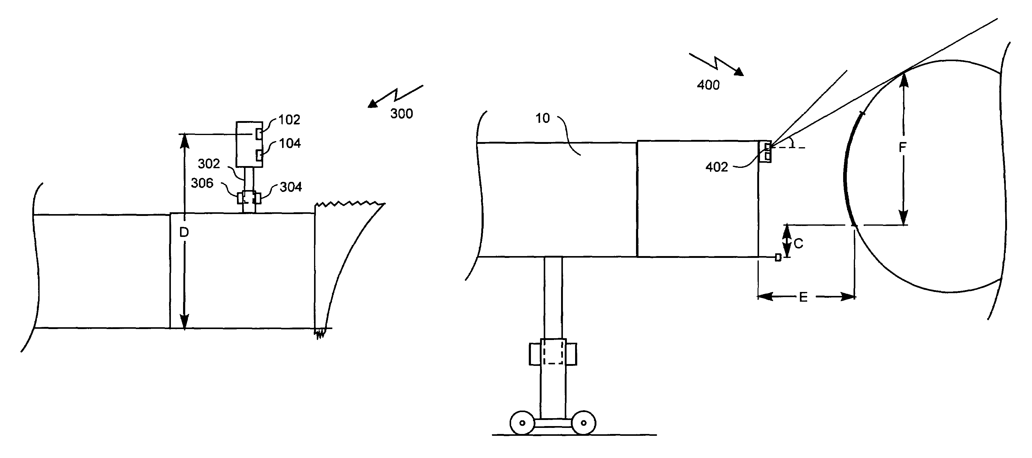
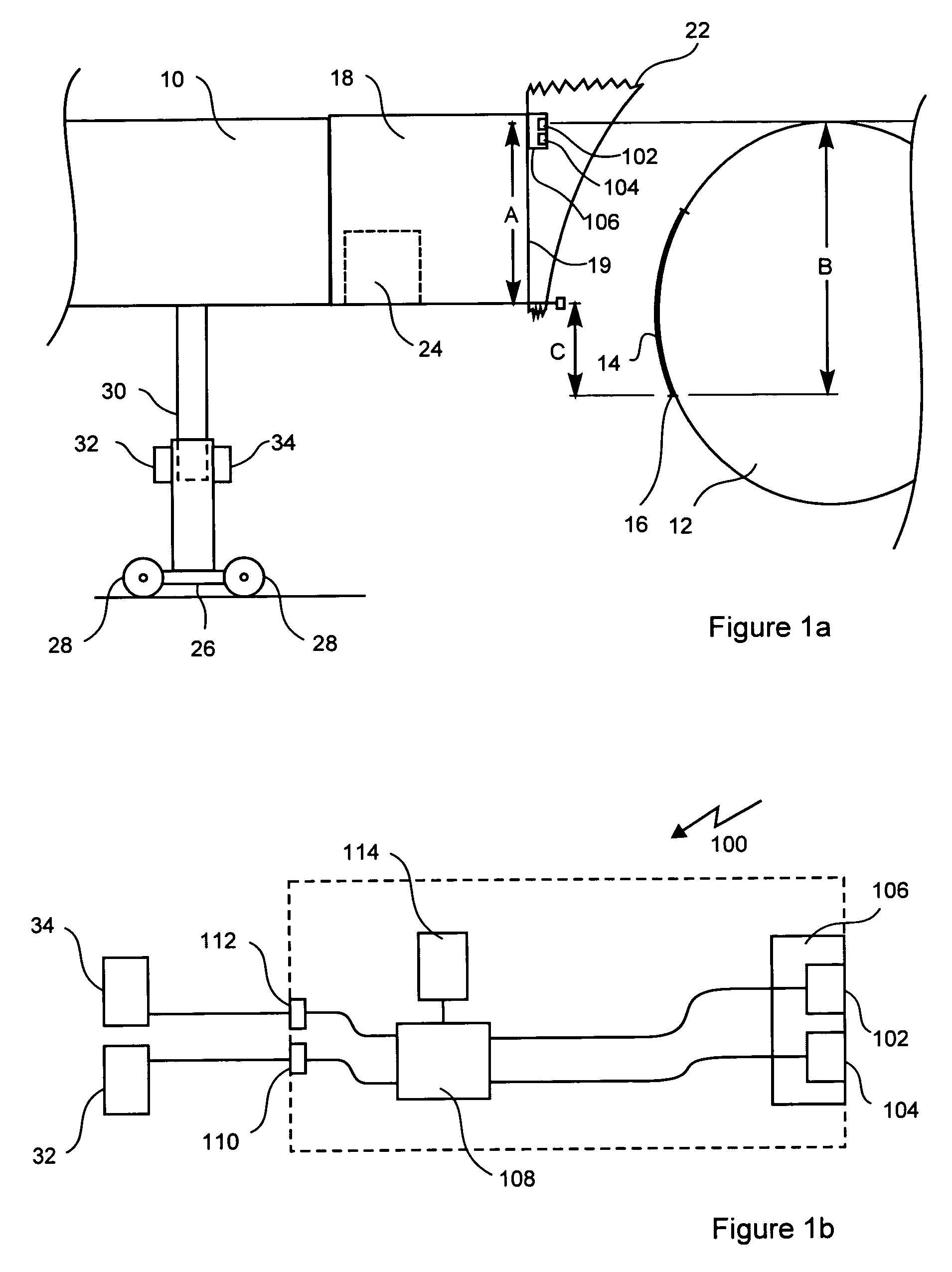
[0030]Referring to FIG. 1a, a schematic side view of a passenger loading bridge 10 is shown. The passenger loading bridge 10, which is identically referred to as a moveable bridge, is equipped with a system 100 for automated elevational adjustment, as is shown in detail in FIG. 1b. Also shown in FIG. 1a is an aircraft 12 with a door 14 having a ...


PUM


Abstract

Vertical alignment of a movable bridge with a doorway of an aircraft is achieved by moving a sensor disposed on the movable bridge in a generally downward direction so as to sense a position of an upper surface of the aircraft. The upper surface of the aircraft has a known elevational relationship relative to the doorway of the aircraft, which is used along with the sensed position to align an aircraft engaging portion of the movable bridge with the doorway. The method accommodates different heights of a same model of aircraft resulting from differences in the aircraft loads and is easily implemented using non-contact sensors.

Description

FIELD OF THE INVENTION[0001]The present invention relates generally to automated passenger loading bridges and in particular to elevational adjustment of an automated passenger loading bridge.BACKGROUND OF THE INVENTION[0002]Passenger loading bridges are used to quickly transport passengers between an airport terminal and an aircraft and to protect the passengers from weather and other environmental influences. For example, a present day passenger loading bridge comprises a plurality of adjustable modules, including: a rotunda, a telescopic tunnel, a bubble section, a cab, and elevating columns with wheel carriage. Of concern to airlines is to ensure that a passenger loading bridge is aligned with an aircraft as rapidly as possible, thereby minimizing the time to complete passenger deplaning as well as the total time the aircraft spends at the airport terminal. As such, manual, semi-automated and fully-automated bridge alignment systems are known for adjusting the passenger loading ...

Claims


Application Information

Patent Timeline
Patent Type & Authority Patents(United States)
IPC IPC(8): E01D15/10
CPCB64F1/305
Inventor HUTTON, NEILIBRAHIM, RAMICONNELLY, MATHEW
Owner AMERIBRIDGE
Learn More