
Coin cell protection against reverse insertion in cell holder

a technology of coin cell and cell holder, which is applied in the direction of cell components, cell component details, electrochemical generators, etc., can solve the problems of shorting the battery, not preventing the application of reverse polarity voltage,

Active Publication Date: 2006-10-10
3SI SECURITY SYST INC
View PDF10 Cites 10 Cited by
  • Summary
  • Abstract
  • Description
  • Claims
  • Application Information

AI Technical Summary

Benefits of technology

[0013]According to another aspect of this invention, there is provided a method for preventing applying a reverse polarity voltage to an electronic circuit from a coin cell used to power such circuit. This method comprises:

Problems solved by technology

A problem with such holders is that, even though they typically include asymmetrically located positive and negative contact electrodes, they do not prevent a reverse polarity voltage to be applied to the electronic circuit they power if the battery is inserted upside down into the holder.
Such reverse polarity voltage may prove damaging to the electronic circuit and create a malfunction, or such contact may result in shorting the battery.

Method used


Image

  • Coin cell protection against reverse insertion in cell holder
  • Coin cell protection against reverse insertion in cell holder
  • Coin cell protection against reverse insertion in cell holder

Examples


Embodiment Construction

[0026]The invention will be described with reference to the figures wherein same numerals are used to identify same elements in all figures. The figures illustrate the invention and are not intended to act as engineering or construction drawings, therefore they are not to scale and do not include all elements that may be included in such drawings, as inclusion of such elements would unduly clutter the drawings.

[0027]The invention will next be described with reference to its application in an alarm device such as an alarm device used by the banking industry to maculate currency. Even though the invention will be described with specific reference to a particular application and related environment where the invention may be used, such description is provided to facilitate an understanding of the invention by providing a specific framework and background for its use and is not intended to limit the use of this invention to a particular alarm circuit or an alarm circuit only.

[0028]In or...


PUM

PropertyMeasurementUnit
conductiveaaaaaaaaaa
dimensionsaaaaaaaaaa
thicknessaaaaaaaaaa

Abstract

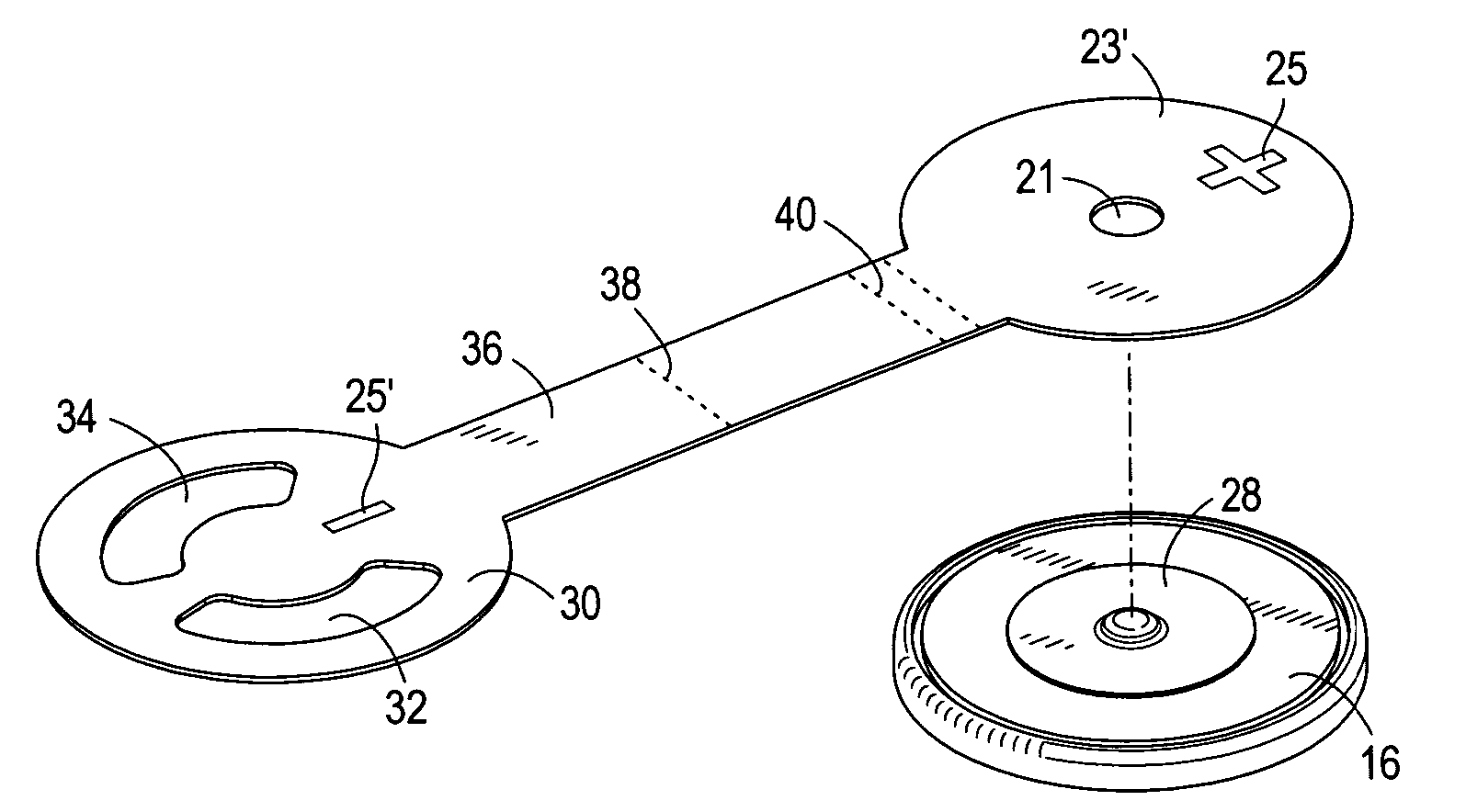
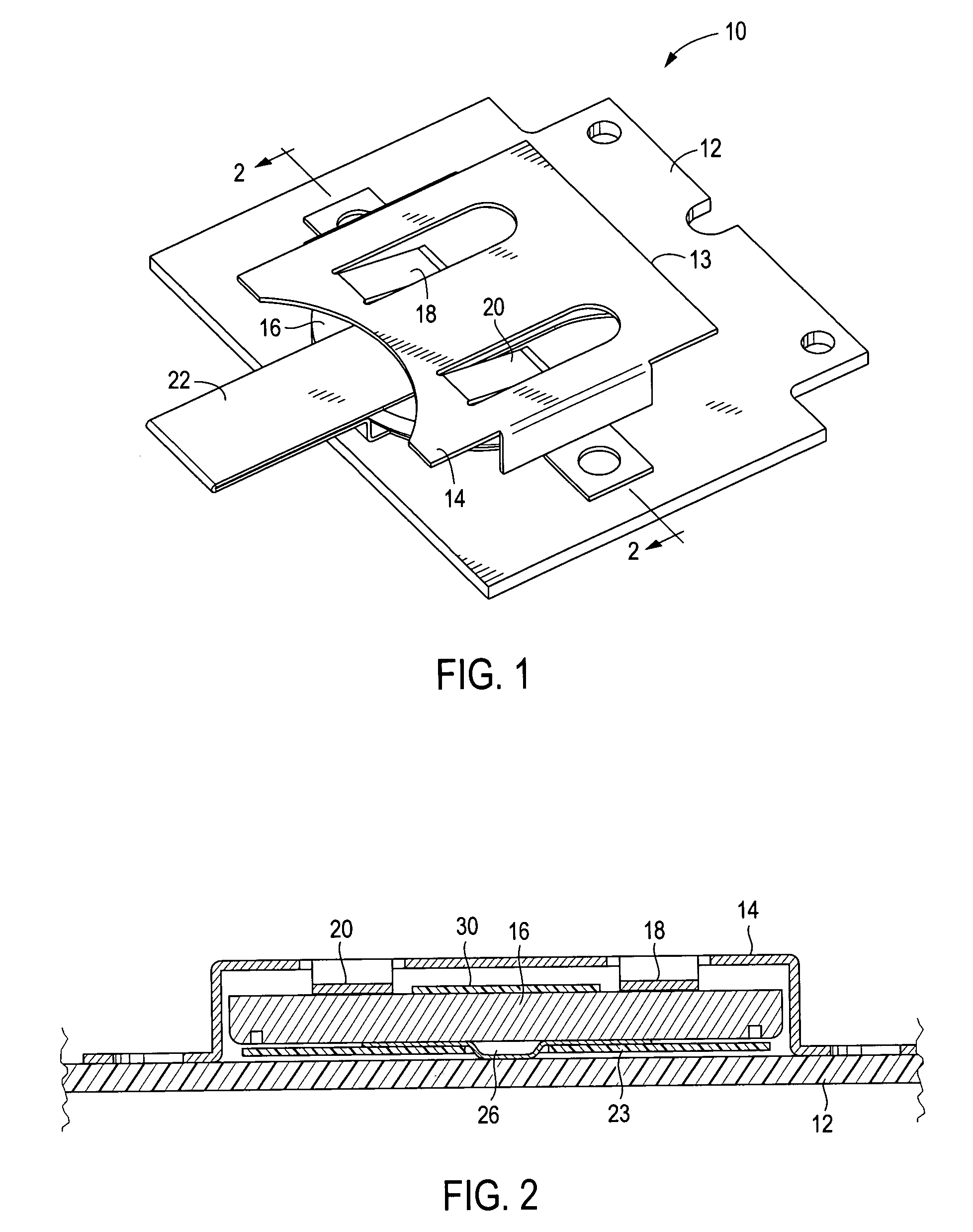
A method and associated apparatus for preventing applying a reverse polarity voltage to an electronic circuit from a coin cell used to power such circuit by providing a first insulating wafer over the top conductive surface of a coin cell and a second insulating wafer over the bottom conductive surface of the cell. The first wafer has a central opening and the second wafer is designed to cover the portion of the bottom conductive surface corresponding to the opening of the first wafer so that when the two wafers of the protection system are placed over the coin cell with the first wafer and the insulating area positioned on the top and bottom conductive surfaces respectively, the insulating area extends fully under the first opening.

Description

CROSS REFERENCE TO RELATED APPLICATIONS[0001]This application claims the benefit of priority to U.S. Provisional Application No. 60 / 408,355, filed on Sep. 5, 2002, the contents of which are incorporated herein by reference in their entirety.FIELD OF THE INVENTION[0002]This invention relates to a protection method and system for a coin type battery (coin cell) used in powering an electronic circuit, and more particularly for a device that prevents a coin cell incorrectly inserted in a holder to electrically connect with the electronic circuit.BACKGROUND OF THE INVENTION[0003]Coin type batteries or coin cells, as are commonly known, are used in numerous applications to power electronic circuits. A coin cell typically comprises small, usually round structure having a top conducting surface that acts as a first polarity electrode contact and a bottom conductive surface which acts as a second polarity contact. Typically the surfaces form the full upper and lower parts of the cell casing,...

Claims


Application Information

Patent Timeline
Patent Type & Authority Patents(United States)
IPC IPC(8): H01M2/10H01M2/34H05K3/30
CPCH01M2/1038H01M2/342H05K3/301H01M50/216H01M50/597Y02E60/10
Inventor BARTHOLF, JOELPOORBAUGH, MICHAEL LARRY
Owner 3SI SECURITY SYST INC
Learn More