
Phase shift bridge converter using clamp circuit connected to the center-tap of the transformer on the secondary side

a converter and clamp circuit technology, applied in the direction of electric variable regulation, process and machine control, instruments, etc., can solve the problems of high voltage stress large switching loss in the rectification stage, and increase in the conductance loss due to high circulation current, so as to reduce the burden of the output inductor and reduce the switching loss of the rectifier

Active Publication Date: 2020-08-11
KOREA ADVANCED INST OF SCI & TECH
View PDF6 Cites 0 Cited by
  • Summary
  • Abstract
  • Description
  • Claims
  • Application Information

AI Technical Summary

Benefits of technology

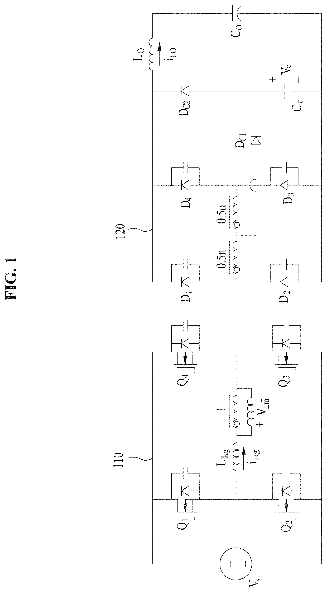
[0007]An embodiment of the present invention provides a converter capable of improving problems, such as a high circulation current, severe voltage stress and a switching loss on the secondary side, and a large output filter, that is, disadvantages of the existing PWM full bridge converters. The proposed converter can obviate a circulation current, can lower voltage stress on the secondary side, and can reduce a switching loss of a rectification stage through a structure in which a clamping circuit having an electric condenser and an rectifier is connected to a center-tapped clamp circuit on the secondary side of a transformer.
[0009]The secondary-side circuit removes a circulation current, lowers voltage stress of the secondary-side circuit, and reduces a switching loss of the secondary-side circuit and the size of an output filter through the structure in which the clamping circuit is connected.
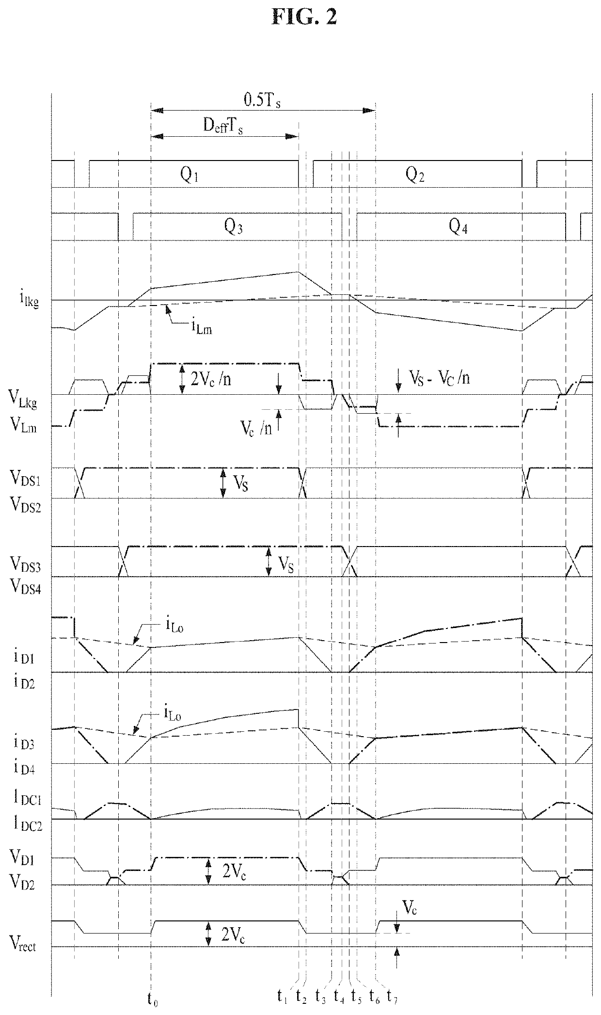
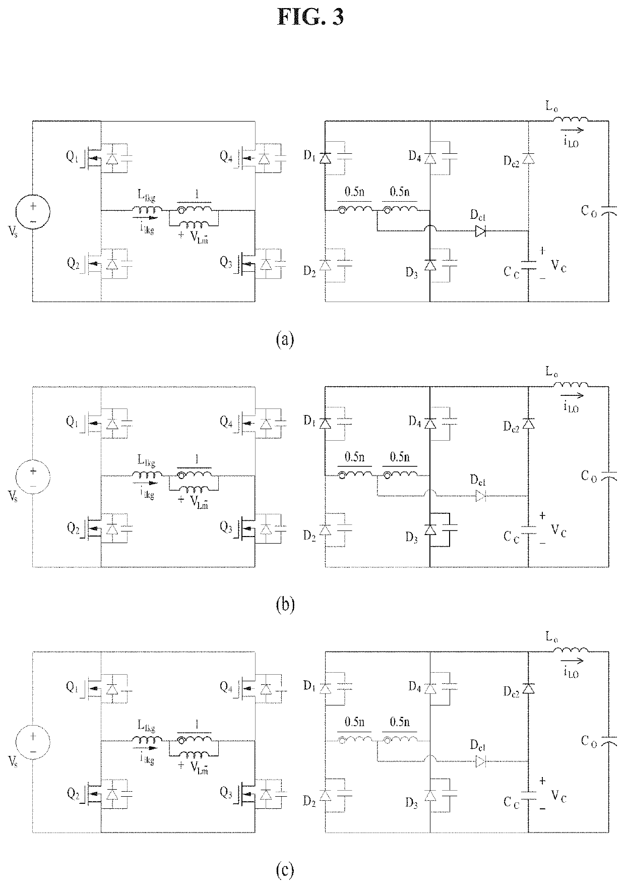
[0012]In the secondary-side circuit, an output inductor starts to be reset right after the commutation of the current from the first rectifier diode and the third rectifier diode to the second clamping diode is started, a voltage applied to the output inductor is reduced as much as a clamp voltage to decrease a burden of the output inductor, the first rectifier diode and the third rectifier diode are turned off by all output currents flow through only the second clamping diode, and an inverse voltage equivalent to the clamp voltage is applied to reduce a switching loss of the rectifier diode.
[0018]The step of resetting an output inductor right after the commutation of the current from the first rectifier diode and the third rectifier diode to the second clamping diode comprises the steps of reducing a voltage applied to the output inductor as much as the clamp voltage to decrease a burden of the output inductor, and turning off the first rectifier diode and the third rectifier diode by all output currents flowing through only the second clamping diode and applying an inverse voltage equivalent to the clamp voltage to reduce a switching loss of the rectifier diode.

Problems solved by technology

However, when the PWM PSFB is applied to a battery charger for electric vehicles, the following disadvantages may be present.
First, a conduction loss increases due to a high circulation current because the range of an output voltage is very wide.
Voltage stress in a rectification stage seriously increases and a switching loss occurring in the rectification stage is very large because an output voltage is large and a large reverse recovery current flows on the secondary side.
Next, there is a problem in that the size of the output filter stage is increased because the output voltage is large.
However, there is a problem in that the optimal design of a magnetic substance or an electric condenser becomes difficult because an operating frequency is very widely changed with respect to an output voltage range.
However, there are problems in that power density is lowered and the reliability of the circuit is degraded because switches are additionally used.
Research for reducing the switching loss of the rectification stage on the secondary side has been carried out, but there is a problem in that an additional conduction loss and a switching loss occur because the switch is positioned in the path along which power is transferred.

Method used


Image

  • Phase shift bridge converter using clamp circuit connected to the center-tap of the transformer on the secondary side
  • Phase shift bridge converter using clamp circuit connected to the center-tap of the transformer on the secondary side
  • Phase shift bridge converter using clamp circuit connected to the center-tap of the transformer on the secondary side

Examples


Embodiment Construction

[0027]Embodiments of the present invention propose a new full bridge converter capable of improving the disadvantages of the existing phase shift full bridge (PSFB). The embodiments of the present invention are described in detail below with reference to the accompanying drawings.

[0028]FIG. 1 is a circuit diagram of a new PSFB converter using a clamp circuit connected to a center-tapped clamp circuit according to an embodiment of the present invention.

[0029]The proposed new PSFB converter using a clamp circuit connected to a center-tapped clamp circuit has a structure in which a clamping circuit having an electric condenser and a rectifier is connected to the center-tapped clamp circuit of the secondary-side circuit of a transformer. The PSFB converter according to an embodiment of the present invention includes a primary-side circuit 110 configured to include a plurality of inductors connected to one end between a first switch Q1 and second switch Q2 that are connected in series an...


PUM

PropertyMeasurementUnit
output voltageaaaaaaaaaa
voltageaaaaaaaaaa
zero-voltage switchingaaaaaaaaaa

Abstract

Disclosed are a new phase shift full bridge (PSFB) converter using a clamp circuit connected to a center-tapped clamp circuit and an operating method thereof. The new PSFB converter using a clamp circuit connected to a center-tapped clamp circuit includes a primary-side circuit including a plurality of inductors connected to one end between a first switch and a second switch which are connected in series and to one end between a third switch and a fourth switch which are connected in series and a secondary-side circuit using a voltage applied by the primary-side circuit and including a clamping circuit configured with a first rectifier diode, a second rectifier diode, a third rectifier diode, a fourth rectifier diode, a first clamping diode, a second clamping diode and a capacitor in a center-tapped clamp circuit.

Description

CROSS REFERENCE TO RELATED APPLICATION[0001]This application is based on and claims priority under 35 U.S.C. 119 to Korean Patent Application No. 10-2018-0101232, filed on Aug. 28, 2018, in the Korean Intellectual Property Office, the disclosures of which is herein incorporated by reference in their entireties.BACKGROUND OF THE INVENTION[0002]1. Technical Field[0003]The present invention relates to a new phase shift full bridge (PSFB) converter using a clamp circuit connected to the center tap of transformer on the secondary side and an operating method thereof.[0004]2. Description of the Related Art[0005]A pulse with modulation (PWM) phase shift full bridge (PSFB) is widely applied in the power range of several kW for a battery charger. The PWM PSFB has advantages in that primary switches can achieve a zero-voltage switching turn-on operation and can be simply controlled compared to a frequency-modulation converter. However, when the PWM PSFB is applied to a battery charger for ele...

Claims


Application Information

Patent Timeline
Patent Type & Authority Patents(United States)
IPC IPC(8): H02M3/335H02M7/487
CPCH02M3/33592H02M7/487H02M3/3376H02M1/0051H02M1/0058H02M1/0064Y02B70/10H02M3/335H02M1/0054
Inventor MOON, GUN WOOLIM, CHEON-YONG
Owner KOREA ADVANCED INST OF SCI & TECH
Learn More