Eureka AIR delivers breakthrough ideas for toughest innovation challenges, trusted by R&D personnel around the world.

Loudspeaker

a loudspeaker and amplifier technology, applied in the field of loudspeakers, can solve the problems of poor performance, obvious complexity, and the inability of digital loudspeakers to take full advantage of 24-bit fidelity, and achieve the effect of avoiding rapid changes in gain to each loudspeaker and high absolute sound levels

Inactive Publication Date: 2006-10-03
QINETIQ LTD
View PDF11 Cites 5 Cited by
  • Summary
  • Abstract
  • Description
  • Claims
  • Application Information

AI Technical Summary

Benefits of technology

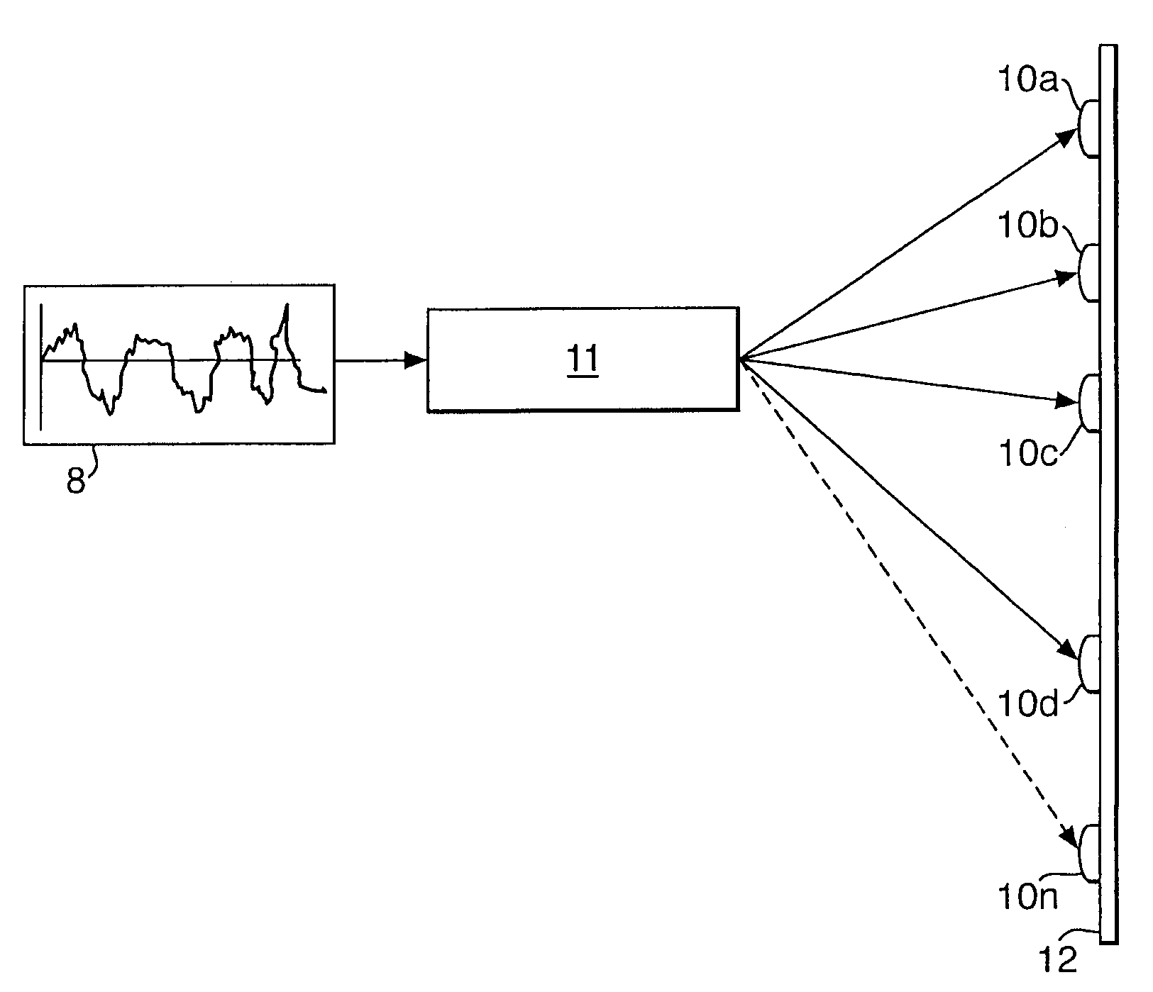
[0015]Panel-form loudspeaker technology is able to take advantage of digital fidelity because it is able to inherently produce very high absolute levels of sound. By using a panel-form loudspeaker combined with a plurality of analogue drivers or exciters it is possible to overcome the problems of complexity, interaction effects and loudness which limit the benefits of existing solutions. Prior art devices have suggested the use of more than one driver for a single loudspeaker, but none of them have recognised the need to control how these drivers interact to obtain the benefits of the present invention.
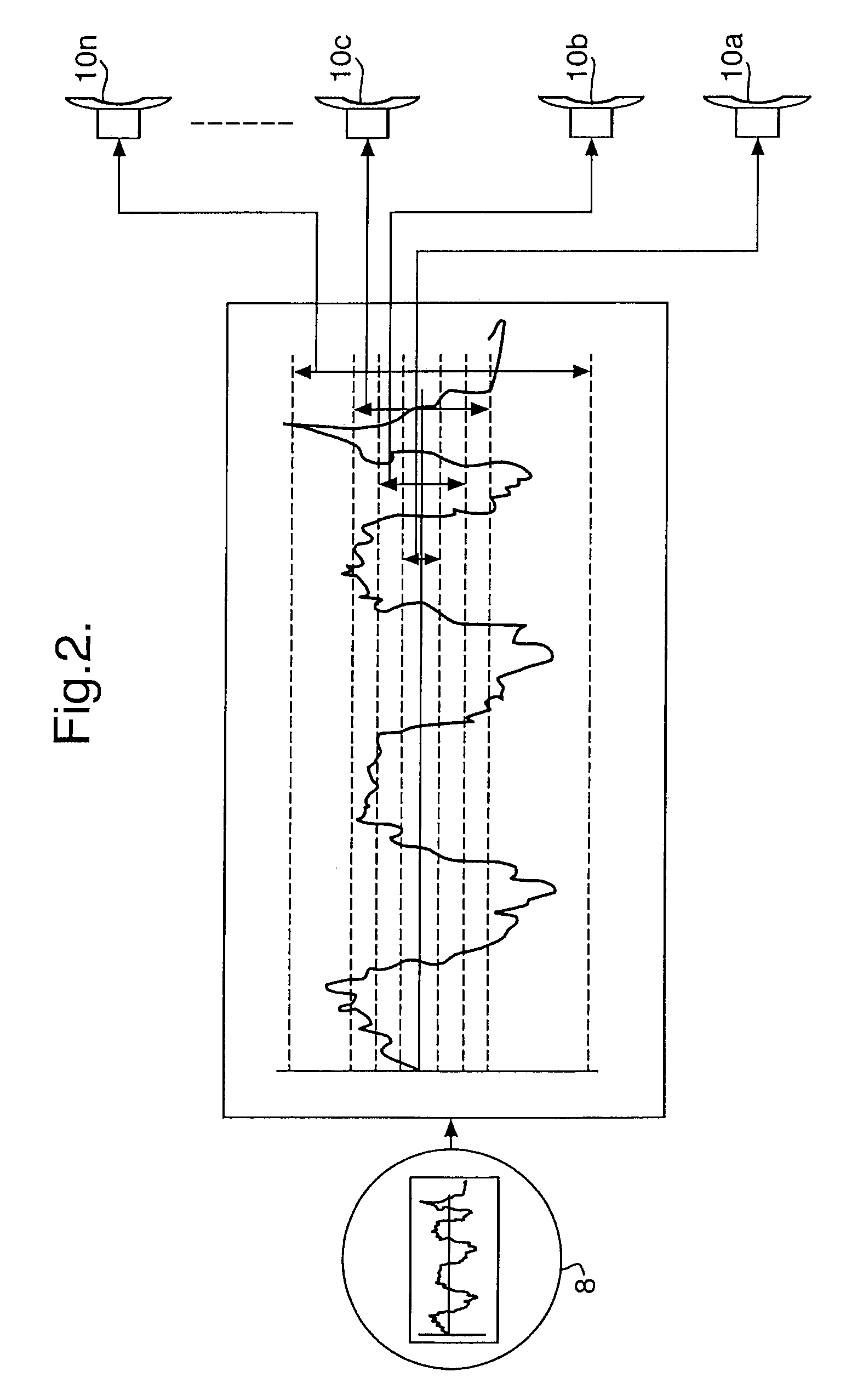
[0016]Since the loudest elements of music signals tend to occur at the lowest frequencies, the width of the window can be chosen to properly produce the necessary low frequency signals whilst avoiding rapid changes in gain to each loudspeaker.

Problems solved by technology

However, these suffer from obvious complexity and poor performance associated with the interaction effects between the different devices, which have discouraged widespread use of such systems.
A further problem is the inability of most loudspeakers to reproduce realistic absolute levels of sound (up to say 120 dB at 1 m without distortion), so such digital loudspeakers cannot take full advantage of the 24-bit fidelity.
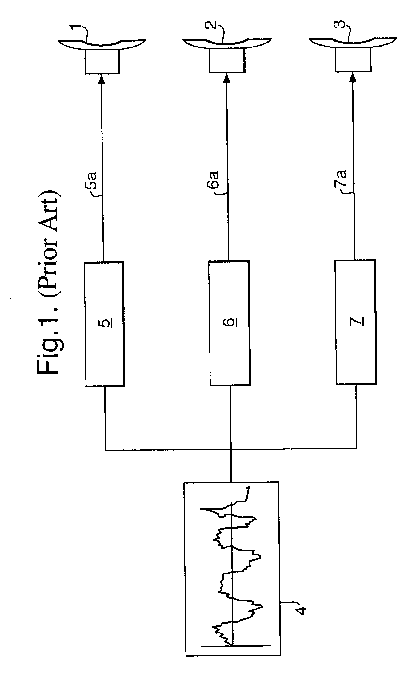
A conventional loudspeaker system, such as that shown in FIG. 1, will suffer distortion and other detrimental effects if the dynamic range supplied to any of the drivers / loudspeakers 1, 2 or 3 exceeds much more than 100 dB.
Note, although conventional speakers can be constructed to have a dynamic range of approaching 120 dB they are very expensive.

Method used


Image

  • Loudspeaker
  • Loudspeaker
  • Loudspeaker

Examples


Embodiment Construction

[0018]At low frequencies the acoustic pressures produced by the action of each active driver will tend to add in a linear fashion. In order to ensure that the combined output from all drivers is correct a control signal can conveniently be applied to the linear time signal to maintain the sum of the linear time output equal to the required signal output.

[0019]In contrast, at high frequencies the acoustic pressures produced by the action of each active driver will add in a power manner. Therefore in order to ensure that the combined power output is correct a control signal can conveniently be applied to a suitable squared time signal such that the sum of the acoustic power output is equal to the desired power output. This is beneficial at the higher frequencies where drivers tend to act independently of one another.

[0020]Preferably, the controller operates in both linear and power signals, such that at low frequencies the controller maintains the linear sum, whilst at high frequencie...


PUM


Abstract

Conventional analog loudspeakers have a limited dynamic range as compared to the available dynamic range of digital recordings. Digital recordings use up to 24 bits and this implies a dynamic range of 141 dB. Digital loudspeakers, involving 2N single bit devices (with N=24, this number is 1.7×10⁷) have been proposed. The present improvement is the provision of at least one loudspeaker, a plurality of analog drivers and the audio input supplied to a control processor which in turn drives one or more of the plurality of independent analog drivers. The number of drivers in operation at any one time is determined by the amplitude of the input audio signal to the control processor.

Description

[0001]This application is the U.S. national phase of international application PCT / GB02 / 00483 filed 4 Feb. 2003, which designated the U.S.BACKGROUND OF THE INVENTION[0002]1. Field of the Invention[0003]This invention relates to loudspeakers and in particular to loudspeakers with improved dynamic range as compared to existing loudspeakers.[0004]2. Discussion of Prior Art[0005]Conventional (or single input) loudspeaker systems can be defined as systems in which the master drive signal may be passed to a plurality of drivers, but for which, at any particular frequency the relationship between the signals passed to each driver is fixed. A driver in this context could mean an electro-magnetic induction coil (as used in conventional loudspeakers) or a piezo-electric pad or any other device that can cause a panel-form loudspeaker or a loudspeaker cone to move.[0006]FIG. 1 shows a conventional loudspeaker system comprising three drivers / loudspeakers 1, 2, 3. A master signal 4 is split by fi...

Claims


Application Information

Patent Timeline
IPC IPC(8): H04R29/00H03G3/00H03G5/00H03G9/00H04R25/00H04R1/00H04R7/04
CPCH04R3/12H04R7/045
Inventor HERON, KENNETH HNASH, MALCOLMPAYNE, ANDREW P
Owner QINETIQ LTD
Why Eureka
Eureka Blog
Learn More