
Electrical conducting system

Inactive Publication Date: 2006-10-03
WEATHERFORD TECH HLDG LLC
View PDF67 Cites 59 Cited by
  • Summary
  • Abstract
  • Description
  • Claims
  • Application Information

AI Technical Summary

Benefits of technology

[0006]The object of the present invention is to provide an appar

Problems solved by technology

Such a system is vulnerable to poor connections between the abutting contact rings.
Another disadvantage of this system is that the connection between the amoured cable and the contact rings are subjected to borehole pressure and are susceptible to fail.
Such linkage, whilst reducing the chance of bad connections, is not suitable for all types of telemetry and power transfer.

Method used


Image

  • Electrical conducting system
  • Electrical conducting system
  • Electrical conducting system

Examples


Embodiment Construction

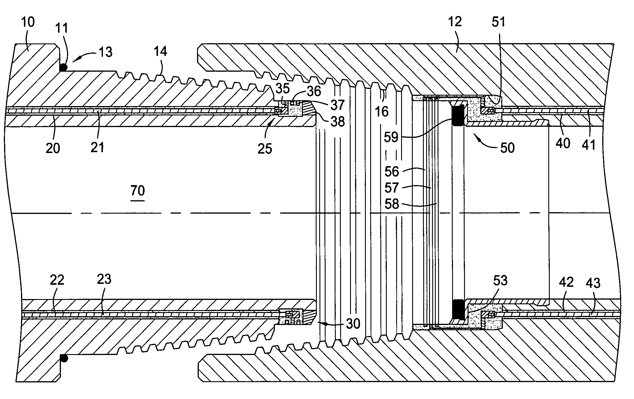
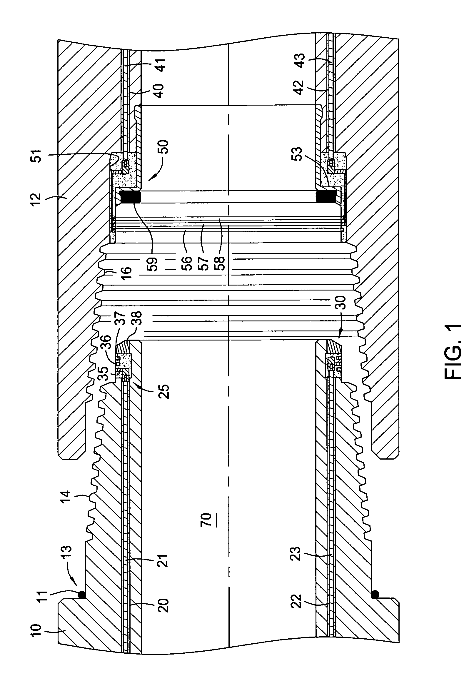
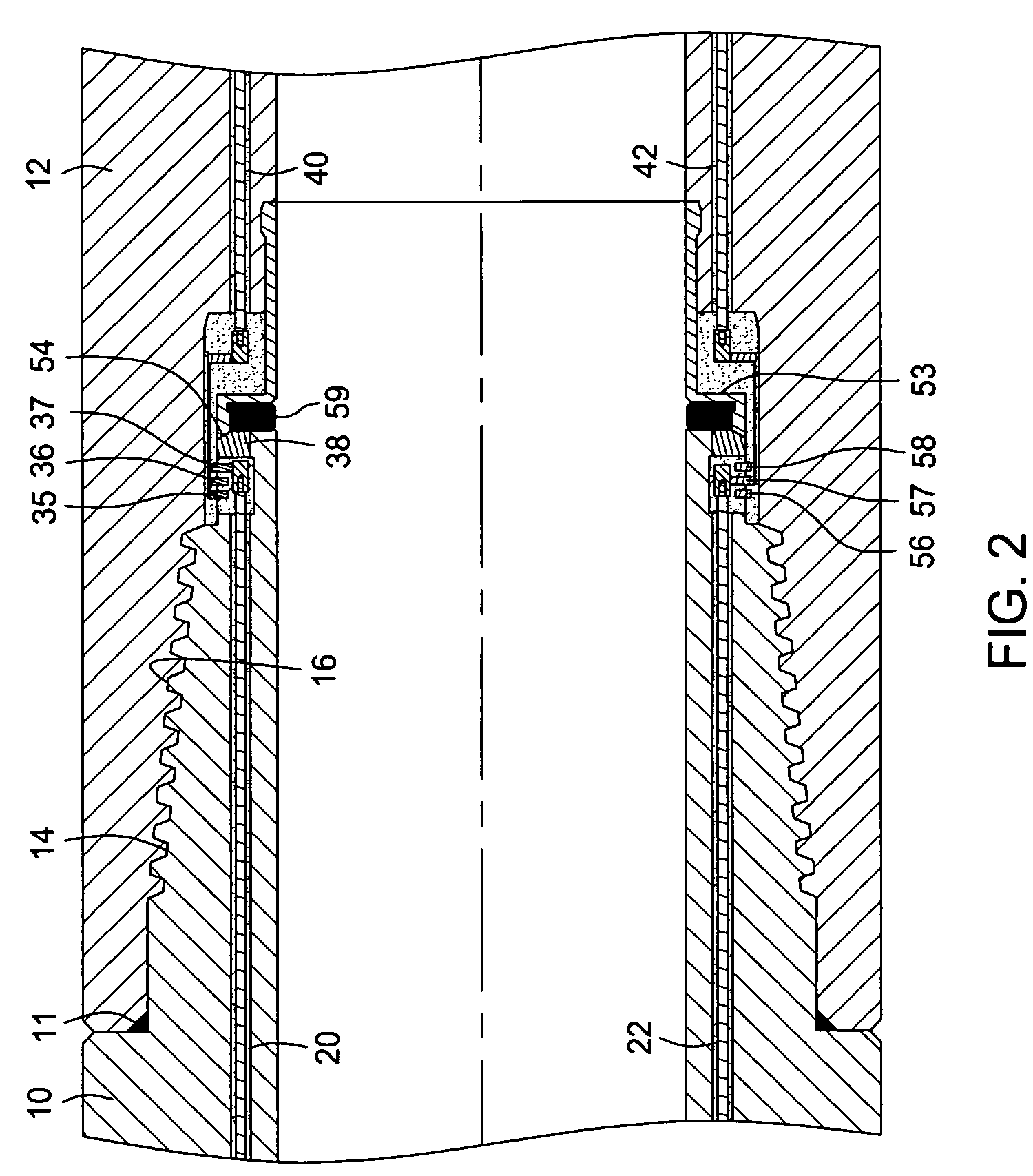
[0046]Generally, in the drawings, parts made from an insulating material (except for non-metal seals, which are black) are hatched with a dot pattern; parts, i.e. conductors, drill pipe, etc., usually made from metal (except for fasteners) are conventionally hatched (where clarity and size allow); and fasteners, i.e. bolts, screws, sockets, plugs, etc., are not hatched. FIG. 1 shows opposing ends of two adjacent drill pipe sections 10, 12. One drill pipe 12 has a female receiving thread 16, which is engaged by rotation of the corresponding male thread 14 of the other drill pipe 10. Each drill pipe has three bores drilled longitudinally inside the drill pipe wall, equally spaced around the radius of the drillpipe section (when spaced at 120° around the radius of the drill pipe, a longitudinal section taken centrally through the drill pipe section would not show two bores; two bores 20, 22 are here shown to better illustrate the nature of the connections).

[0047]The bore 20 opens at th...


PUM


Abstract

A generally tubular drill string has a conductive path over a plurality of drill pipe section (10). Each drill pipe section has a first end and a second end, and a wall, and the first end has a first radial sealing surfaces (11) and the second end has a corresponding second radial surfaces (59), such that when the first or second end of one drill pipe section is engaged with the second or first end respectively of another drill pipe section, at least one seal is formed. The drill pipe includes at least one conductor (21) disposed inside it, this conductor being connected to a first contact means at the first end and a corresponding contact means at the second end of each drill pipe section. Ingress protection means (240) are provided to protect the contact means from ingress from inside or outside of the drill pipe section. The ingress protection means comprises a sealed volume surrounding the contact means.

Description

BACKGROUND OF THE INVENTION[0001]The present invention relates to the transmission of power and data within a well bore, in particular, through a drillstring.[0002]When drilling a borehole, or performing operations to maintain the borehole or operations associated with the production of oil or gas, it is often desirable to transmit power to various downhole devices, such as drill bits and traction tools. Various instruments can also be included on a drill string in order to gather data concerning the structure of the environment of the borehole, and the performance of the borehole operations and downhole devices. It is advantageous for this data to be transmitted back to the surface along an electrical conductor.[0003]In one cabling system, each drill pipe section includes a contact ring at each end of the section. A passageway between each ring accommodates an armoured conductor which connects the two contact rings. When the drill pipe sections are made up in a drill string, the co...

Claims


Application Information

Patent Timeline
IPC IPC(8): H01R4/60E21B17/02
CPCE21B17/028E21B17/0285
Inventor HEAD, PHILIP
Owner WEATHERFORD TECH HLDG LLC
Learn More