
Material/equipment handling assembly

a technology for handling assembly and equipment, applied in the direction of roofs, transportation items, loading/unloading vehicle arrangment, etc., can solve the problems of reducing the vacuum effect, reducing the efficiency of the vacuum effect, so as to achieve effective isolation, convenient access, and effective collection and discharge

Inactive Publication Date: 2006-09-26
MILLS FRANK O
View PDF29 Cites 7 Cited by
  • Summary
  • Abstract
  • Description
  • Claims
  • Application Information

AI Technical Summary

Benefits of technology

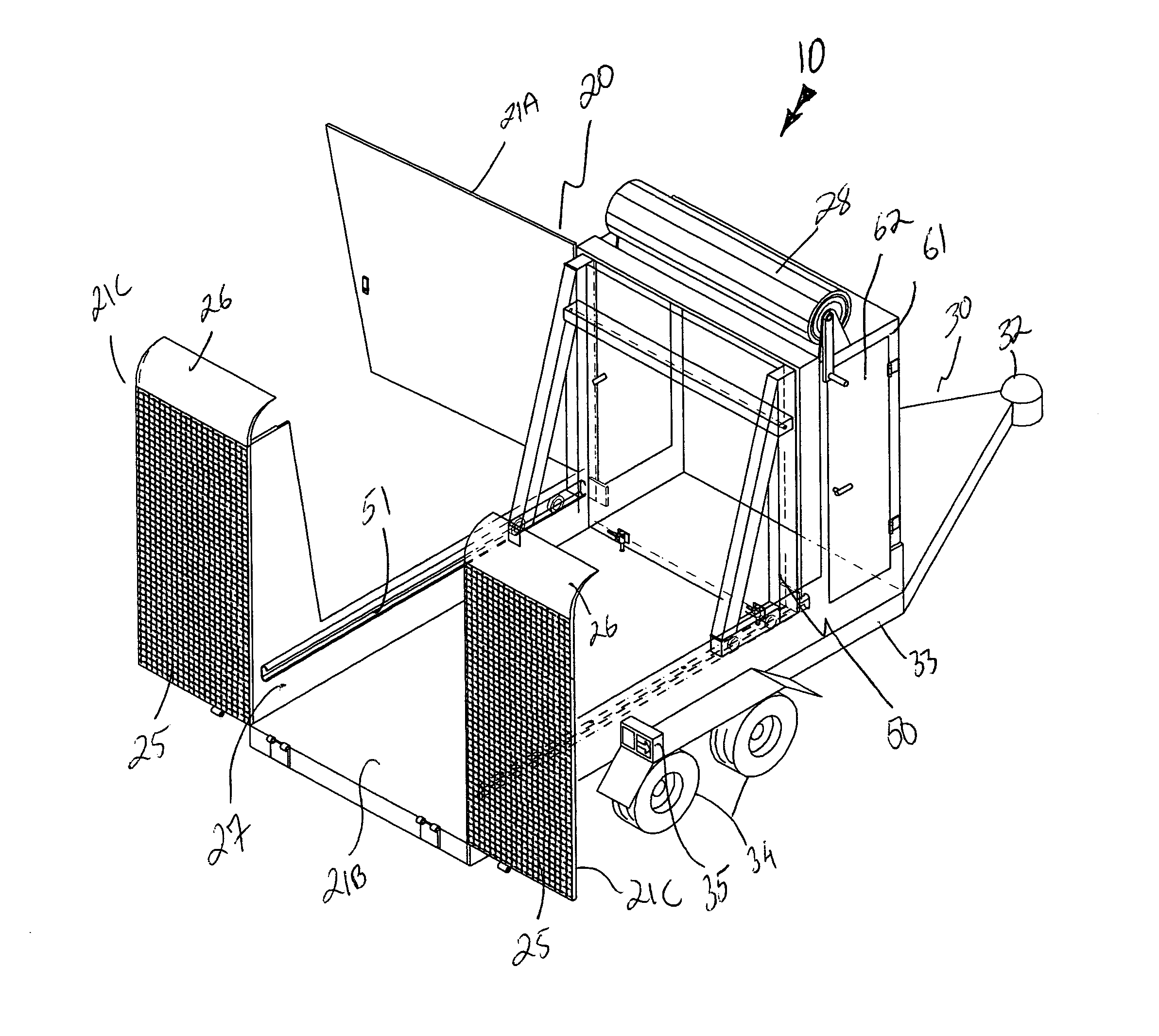
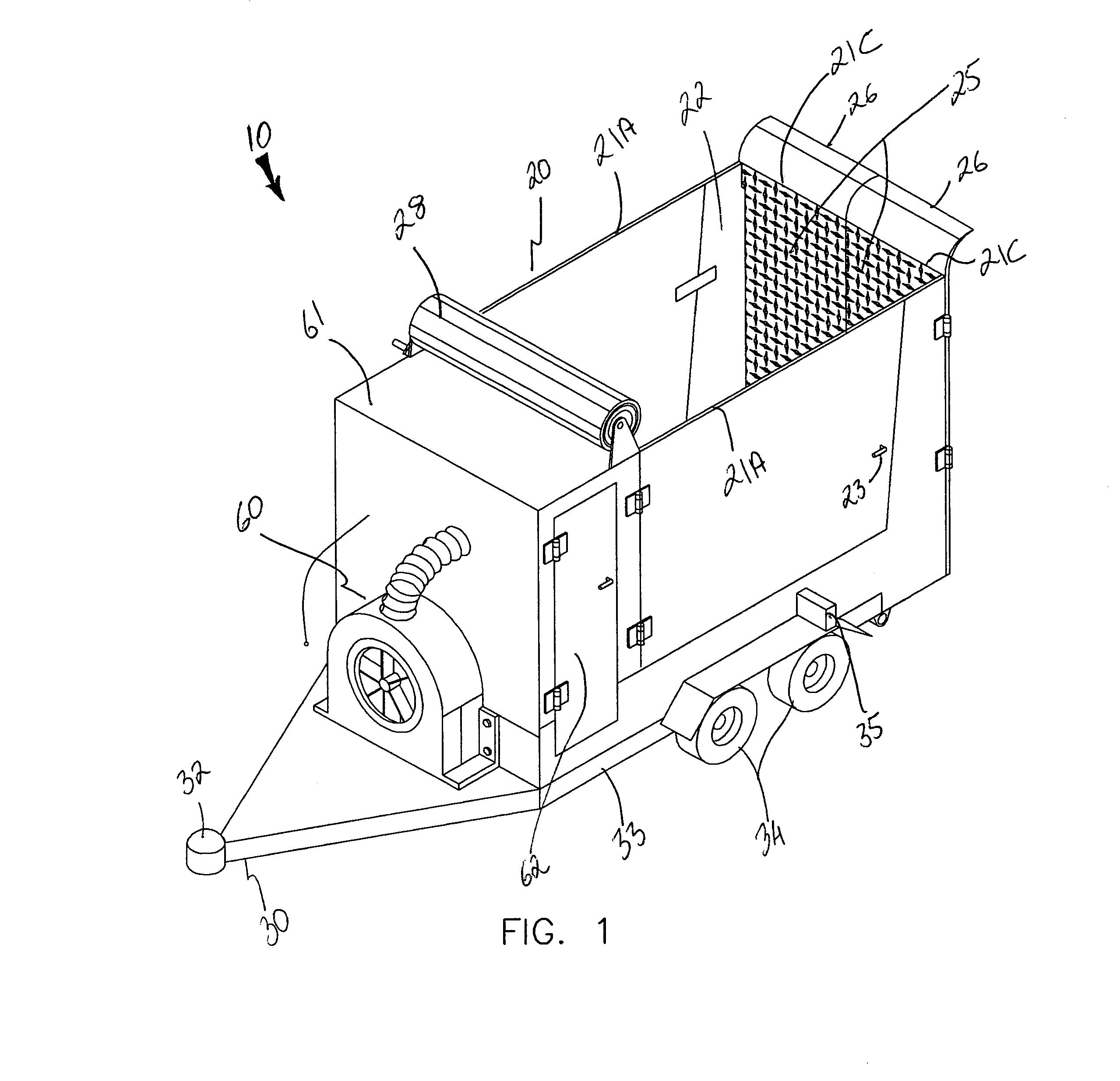
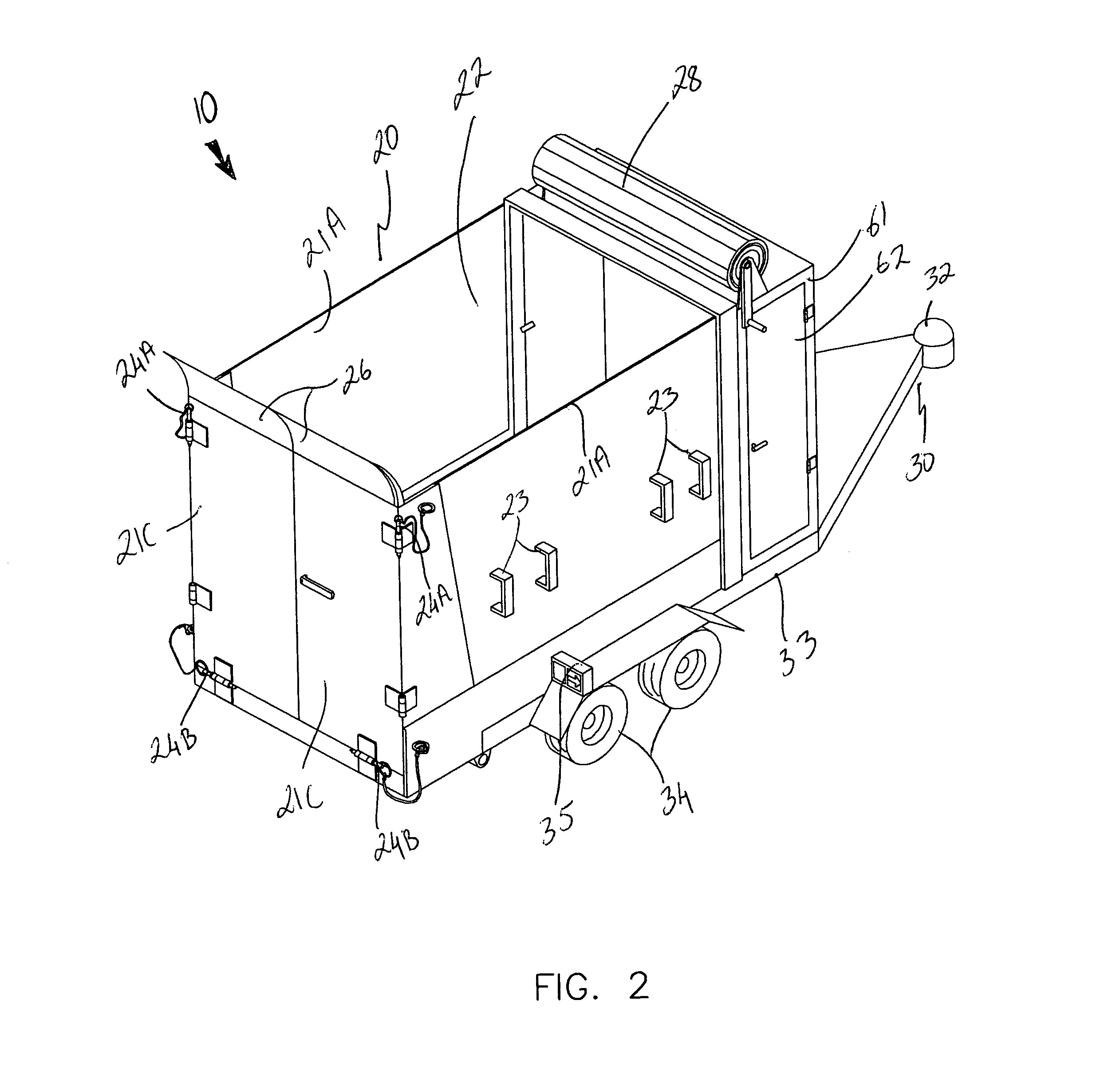
[0013]The trailer assembly includes a body that has a plurality of operably connected sidewalls for defining a cavity therebetween such that an operator can conveniently selectively access the cavity from alternate sides of the body. Selected ones of such sidewalls are pivotally coupled to the body and selectively adaptable between loading and unloading positions such that materials and equipment stored within the cavity can be removed outwardly from the body during operating conditions. Such selected sidewalls preferably include a plurality of handles attached thereto for conveniently assisting the operator to swivel the selected sidewalls between open and closed positions. Another one of the sidewalls defines a substantially planar bottom surface of the body for effectively supporting the material and equipment thereabove.
[0018]A mechanism is included for separating a plurality of loads stored within the cavity such that the loads can be effectively isolated during transport. Such a separating mechanism is removably positional within the cavity and slidably adjustable along a longitudinal length of the body such that a pair of contiguous cavity portions can advantageously be selectively adapted between alternate dimensions.
[0019]The separating mechanism preferably includes a plurality of coextensive and chamfered guide rails coupled to an interior surface of the body and extends parallel to the longitudinal length thereof such that the chamfered guide rails are equidistantly spaced apart from a central axis of the body. A mobile wall is slidably registered along the chamfered guide rails for effectively parting the plurality of loads housed within the cavity. Such a mobile wall includes a pair of oppositely spaced support frames and an access door medially nested therebetween wherein the access door can be articulated between raised and lowered positions while the mobile wall is situated within the cavity. The access door includes a plurality of quick-release fasteners attached thereto for maintaining the access door at a locked position during operating conditions. A plurality of rollers are attached to the support frames for advantageously assisting the operator to glide the mobile wall along the chamfered guide rails.
[0020]A manually operable retractable tarpaulin is laterally registered along a width of the body and adjoins a front end portion of the body such that the tarpaulin can be selectively biased between extended and retracted positions along a top opening of the body. Such a tarpaulin advantageously protects exposed material and equipment during transit.
[0021]The trailer may further include a vacuum mechanism for selectively introducing and discharging particulate materials housed within the cavity. The body further has a hopper section defined within the cavity and juxtaposed adjacent to the front end portion of the body. The vacuum mechanism is in fluid communication with the hopper section wherein the particulate materials can advantageously be effectively collected and discharged from the hopper section without occupying the cavity. Such a hopper section includes a plurality of side doors pivotally connected thereto for allowing the operator to conveniently access the hopper section from an exterior of the body.

Problems solved by technology

In the lawn mowing and construction industries, debris often accumulates at the worksite that hinders other tasks to be performed at the worksite.
However, as the bag fills up, the pores become clogged with debris which substantially blocks the air flow and greatly reduces the vacuum effect, sometimes reducing it to near zero.
In addition, when such fabric bags become clogged, they are subjected to high internal pressure from the blower air stream.
If the blower is very powerful, the bag can rip apart at the seams.
Furthermore, there is no known example in the prior art of knowledge, that allows a trailer equipped with a vacuum device to simultaneously carry other materials and equipment therein.

Method used


Image

  • Material/equipment handling assembly
  • Material/equipment handling assembly
  • Material/equipment handling assembly

Examples


Embodiment Construction

[0031]The present invention will now be described more fully hereinafter with reference to the accompanying drawings, in which a preferred embodiment of the invention is shown. This invention may, however, be embodied in many different forms and should not be construed as limited to the embodiment set forth herein. Rather, this embodiment is provided so that this application will be thorough and complete, and will fully convey the true scope of the invention to those skilled in the art. Like numbers refer to like elements throughout the figures.

[0032]The assembly of this invention is referred to generally in FIGS. 1–7 by the reference numeral 10 and is intended to provide a material / equipment handling assembly. It should be understood that the assembly 10 may be used to transport many different types of materials and equipment, and should not be limited in use to transporting only lawn care materials and equipment.

[0033]Referring initially to FIG. 1, the apparatus 10 includes a body...


PUM


Abstract

A trailer assembly includes a body having a plurality of sidewalls for defining a cavity therebetween. Selected sidewalls are pivotally coupled to the body and selectively adaptable between loading and unloading positions and another sidewall defines a substantially planar bottom surface of the body. The body further includes a hitch section protruding forwardly therefrom. The assembly includes a rigid platform including a plurality of wheels connected thereto. Mechanisms are included for pivoting the body between sloped and horizontal positions and for separating a plurality of loads stored within the cavity respectively. The separating mechanism is removably positional within the cavity and slidably adjustable along a longitudinal length of the body. A manually retractable tarpaulin is laterally registered along a width of the body and adjoins a front end portion of the body for protecting exposed material and equipment during transit.

Description

CROSS REFERENCE TO RELATED APPLICATIONS[0001]Not Applicable.STATEMENT REGARDING FEDERALLY SPONSORED RESEARCH OR DEVELOPMENT[0002]Not Applicable.REFERENCE TO A MICROFICHE APPENDIX[0003]Not Applicable.BACKGROUND OF THE INVENTION[0004]1. Technical Field[0005]This invention relates to a material / equipment handling assembly and, more particularly, to a material / equipment handling assembly for transporting materials, equipment and the like between remote locations.[0006]2. Prior Art[0007]In the lawn mowing and construction industries, debris often accumulates at the worksite that hinders other tasks to be performed at the worksite. These industries, furthermore, require the use of a variety of equipment to perform various tasks properly. As such, the use of one or more trailers is often employed to carry equipment and materials, and to collect debris.[0008]The collection of leaves, grass clippings and other organic debris from lawn mowers into either fabric collector bags, or into rigid c...

Claims


Application Information

Patent Timeline
Patent Type & Authority Patents(United States)
IPC IPC(8): B60P1/16
CPCB60P1/00B60P1/435B60P1/28
Inventor MILLS, FRANK O.
Owner MILLS FRANK O
Learn More