
Telescoping outrigger boom with tube locking mechanisms

a technology of locking mechanism and outrigger, which is applied in the field of outriggers, can solve the problems of affecting the service life of the outrigger,

Inactive Publication Date: 2006-09-26
TACO METALS
View PDF5 Cites 53 Cited by
  • Summary
  • Abstract
  • Description
  • Claims
  • Application Information

AI Technical Summary

Benefits of technology

The system minimizes wear and corrosion, ensures secure locking and alignment, and extends the life of components by reducing internal play and preventing water intrusion, while allowing easy manual operation and secure storage.

Problems solved by technology

Although these outriggers work fine, storing them becomes a problem because of their length, which requires them to be positioned parallel to the hull of the boat, taking up space and often getting in the way.
One of the drawbacks of the internal hair spring and internal spring load design is that at least one of the punched holes in the telescoping tube sections is subjected to stress resulting in hole enlargement (wallowing-out) over time due to the repeated metal to metal pin contact during normal service.
Components in the internal operating locking systems, such as the bullet, can also scratch the tubing and promote corrosion due to the internal pin rubbing against the metal tubing during operation.
This is exasperated by exposure to salt water resulting in shortened component life, especially if regular maintenance is neglected.
While the Wilcox design uses an internal rib inside the telescoping tubes to keep the locking holes inside the tube in alignment, it does not alleviate the potential problem of the locking holes becoming wallowed out due to undesirable movement between the extended tubes.
Furthermore, the design does not use a plastic composition bullet tip, allowing the inner spring activated metallic Bullet Lock to contact the inner metallic wall of the larger outer tube resulting in excessive wear, corrosion, and possible component failure.

Method used


Image

  • Telescoping outrigger boom with tube locking mechanisms
  • Telescoping outrigger boom with tube locking mechanisms
  • Telescoping outrigger boom with tube locking mechanisms

Examples


Embodiment Construction

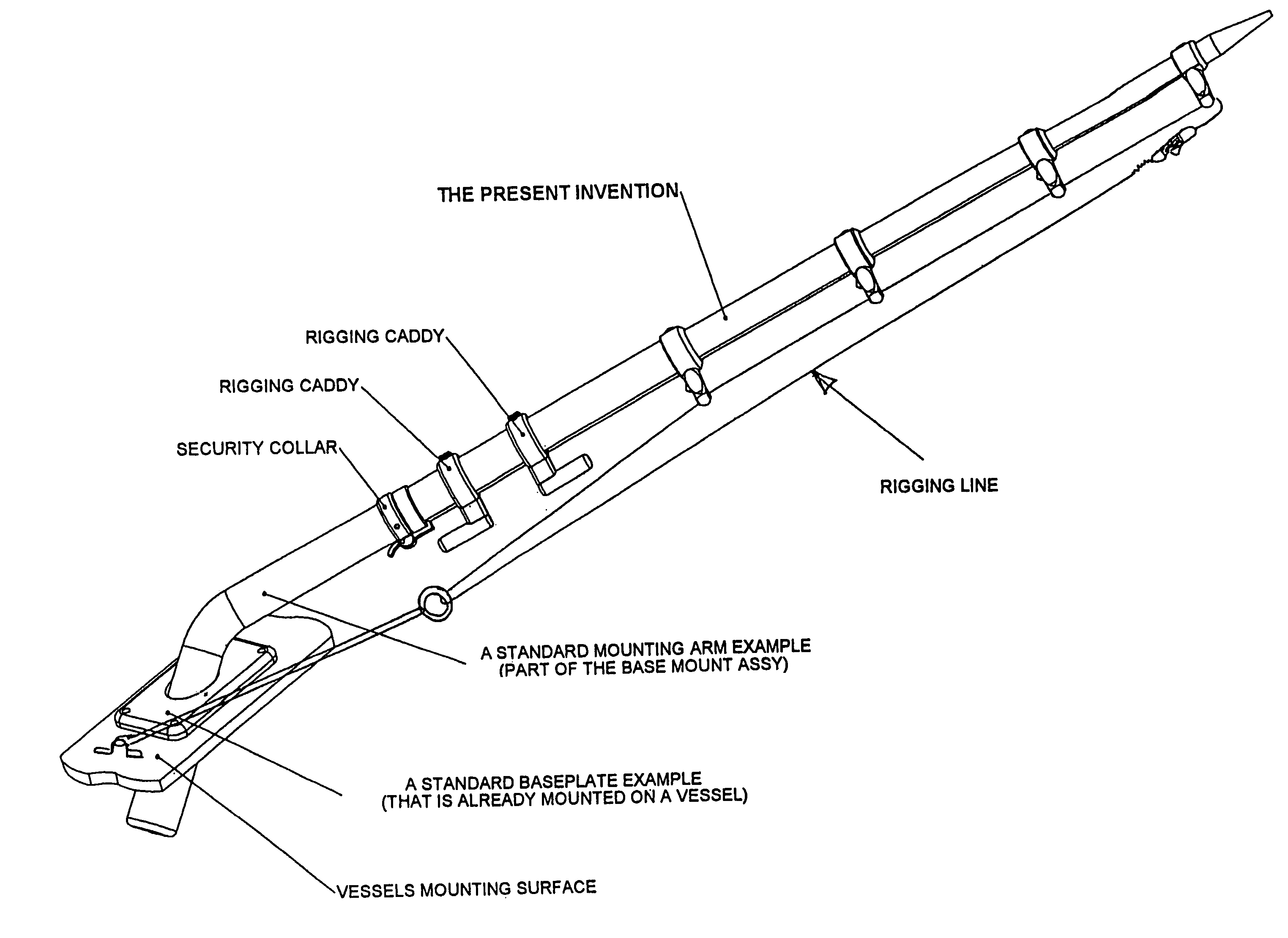
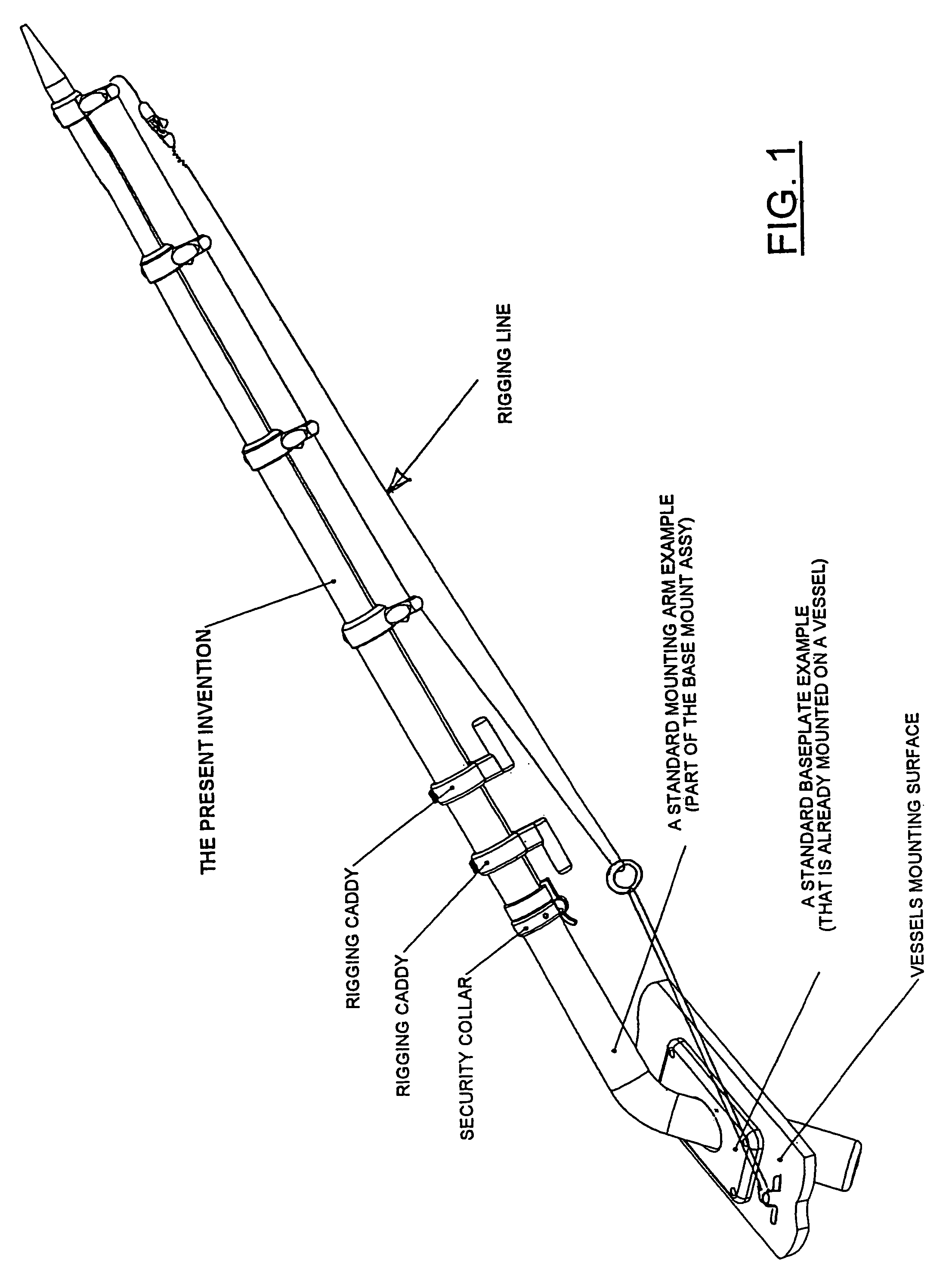
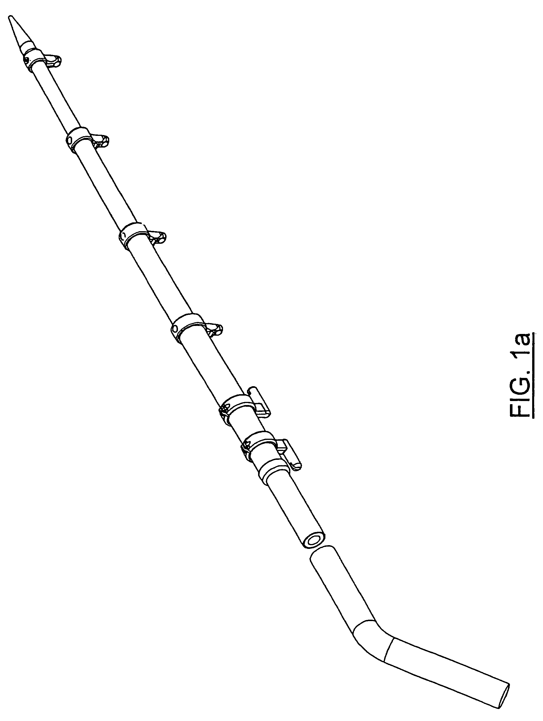
[0093]The present invention details an externally mounted locking mechanism for locking individual tubes of a telescoping outrigger system in place. Additionally, it solves problems encountered in the prior art.

[0094]Two embodiments of the invention are described. The first embodiment encompasses a manually operable externally mounted tube locking mechanism. A second embodiment combines the tube locking mechanism of the first embodiment with a cam lever operated eyelet system.

[0095]One problem described in the background section concerned the wallowing out of the punched holes in the tubular sections of a telescoping boom bullet-type locking system due to repeated metal to metal contact during use. The present invention minimizes this effect by using inner and outer tube sections with an external bullet style lock, a cam lever (in the second embodiment), and an optional cam guide locking ring (in the second embodiment) that helps reduce the inner and outer telescoping tube's interna...


PUM


Abstract

An outrigger assembly for a fishing vessel to extend fishing lines away from the vessel, including a telescopic boom having a plurality of aligned ‘D’ tubes of consecutively smaller diameters that can be individually locked in place when extended and having the smaller tubes telescopically mounted inside larger tubes for storage, first embodiment provides a manually operable locking mechanism using an external shift bullet to lock the tubes in place, and second embodiment combines the locking means of the first embodiment with a cam lever operated eyelet locking system, the eyelets provide support for a fishing rigging, both embodiments protect the locking mechanism from elements found in the environment.

Description

CROSS-REFERENCE TO RELATED APPLICATIONS[0001]This application claims the benefit of U.S. Provisional Application Ser. No. 60 / 502,603, filed on Sep. 12, 2003, entitled TELESCOPING OUTRIGGER BOOM.BACKGROUND OF THE INVENTION[0002]1. Field of the Invention[0003]This invention relates to outriggers that are used on fishing boats typically for fishing line separation while fishing, and specifically to an improved outrigger boom that has a variable length formed in sections that telescope and lock together.[0004]2. Description of Related Art[0005]The use of outriggers on fishing vessels for line separation is well known. Typically, an outrigger is pivotally anchored near the stern of the boat on each side and includes an elongated boom that can be positioned angularly relative to the hull of the vessel. A movable rigging line containing a clip to releasably hold a fishing line is attached to the elongated boom to allow moving the fishing line out along the boom of the outrigger for separat...

Claims


Application Information

Patent Timeline
Patent Type & Authority Patents(United States)
IPC IPC(8): B63B35/14A01K91/08
CPCA01K91/08
Inventor SLATTER, STEPHEN O.
Owner TACO METALS
Learn More