
Apparatus for discovering a powerability condition of a computer network

a technology for computer networks and power conditions, applied in the field of data communication networks, can solve the problems of creating adverse conditions within the computer network itself, permanent damage to the non-remote powerable device, and high risk of damaging any non-remote powerable device on the network,

Inactive Publication Date: 2006-09-19
CISCO TECH INC
View PDF17 Cites 18 Cited by
  • Summary
  • Abstract
  • Description
  • Claims
  • Application Information

AI Technical Summary

Benefits of technology

The invention is about a way to detect if a computer network has a device that can be powered remotely without damaging other devices on the network. This is important because applying power to a network can cause damage or malfunctions to non-remotely powered devices. The invention uses a test signal to determine if a device is remotely powerable and can control when power is applied to the network. This way, the invention can protect the network from damage and ensure that only the necessary devices are powered.

Problems solved by technology

Unfortunately, if a power source (e.g., a power supply) simply applies power to an 802.3 computer network in order to power a remotely powerable device on that network, there is a high risk of damaging any non-remotely powerable device on the network, i.e., a device which does not require and draw remote power.
A conventional non-remotely powerable device typically includes circuitry (e.g., a network termination circuit) that is unable to handle power provided over a computer network.
In the event of remote power application, such circuitry can overheat or burn out resulting in permanent damage to the non-remotely powerable device.
Furthermore, applying power to a computer network that does not require such power runs the risk of creating adverse conditions within the computer network itself.
For example, applying power to an 802.3 network runs the risk of generating broadcast firestorms within the 802.3 network.

Method used


Image

  • Apparatus for discovering a powerability condition of a computer network
  • Apparatus for discovering a powerability condition of a computer network
  • Apparatus for discovering a powerability condition of a computer network

Examples


Embodiment Construction

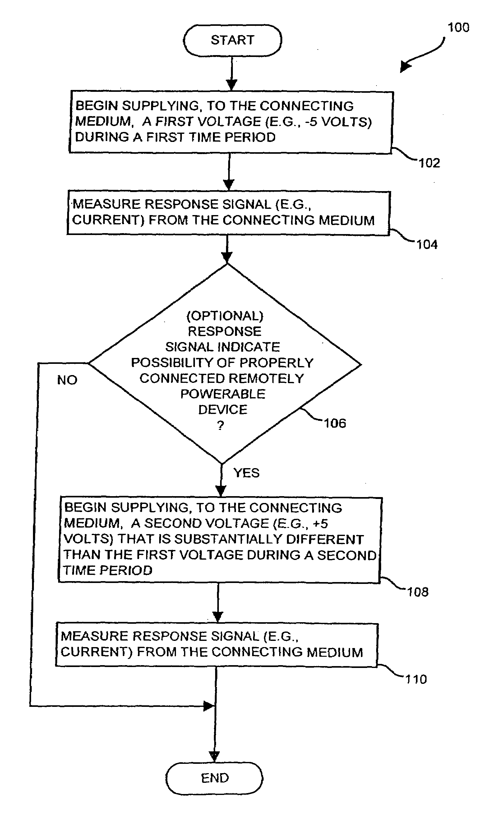
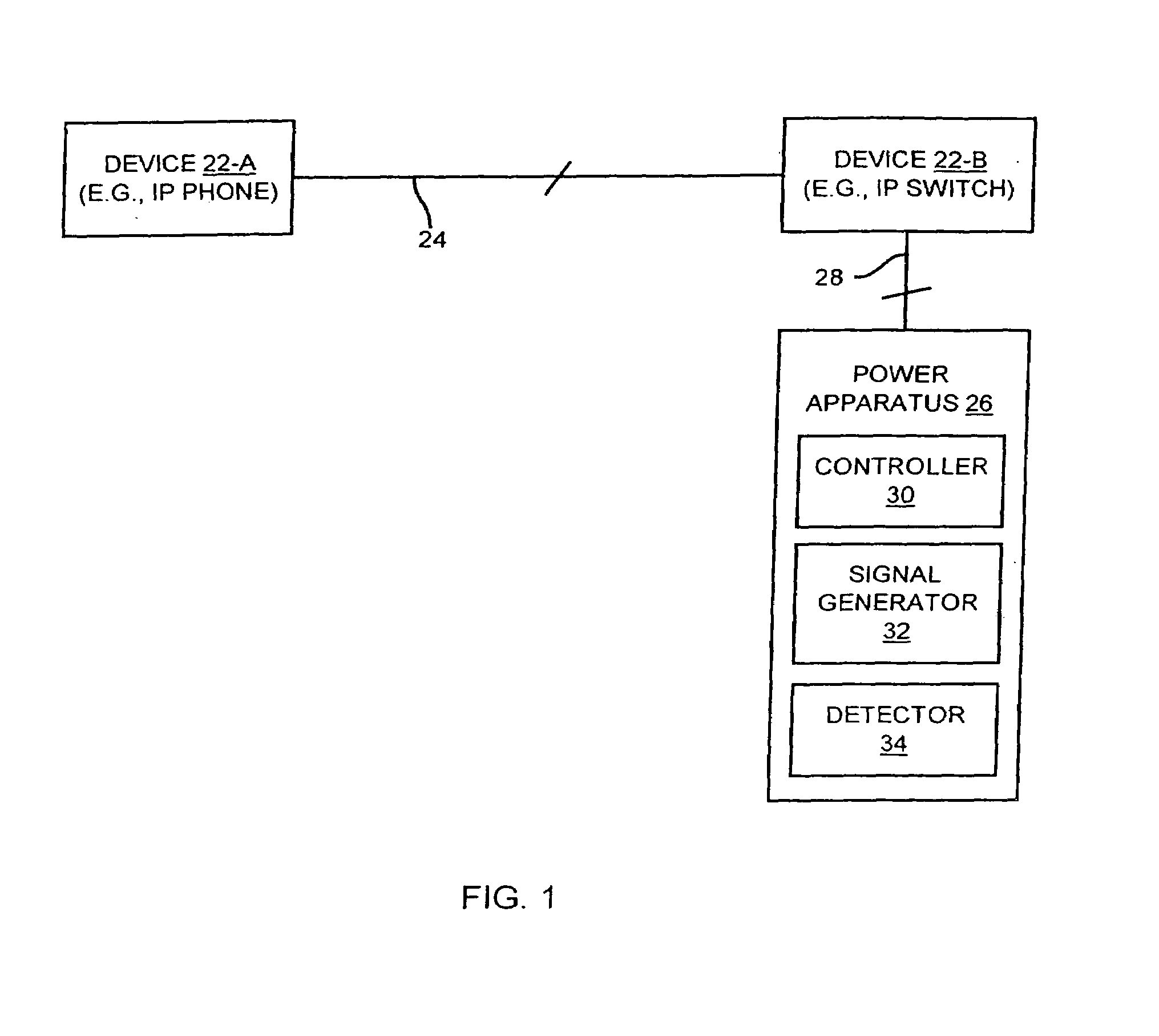
[0027]A remotely powerable device is a device which requires and draws power from a remote power source for normal operation. The invention is directed to techniques for discovering a powerability condition of a computer network such as the existence of a remotely powerable device attached to a connecting medium of the network. Such detection can then control whether a remote power source (e.g., a data communications device such as a switch) provides remote power (e.g., phantom power or direct power) to the network. That is, if it is determined that a remotely powerable device is attached to the network, the remote power source can provide power to the device remotely (e.g., through the connecting medium). However, if no remotely powerable device is discovered, the remote power source can avoid providing power remotely, and thus avoid possibly damaging any non-remotely powerable devices on the network. Such techniques may be employed in data communications devices and other computer...


PUM


Abstract

The invention is directed to techniques for discovering a powerability condition of a computer network such as the existence of a remotely powerable device attached to a connecting medium of the computer network. Such detection can then control whether a remote power source (e.g., a data communications device such as a switch) provides remote power (e.g., phantom power) to the computer network. One arrangement of the invention is directed to an apparatus for discovering a powerability condition of a computer network. The apparatus includes a signal generator, a detector and a controller which is coupled to the signal generator and the detector. The controller configures the signal generator to provide a test signal to a connecting medium of the computer network, and configures the detector to measure a response signal from the connecting medium of the computer network. The controller then indicates whether a remotely powerable device connects to the connecting medium of the computer network based on the response signal. Accordingly, if the apparatus discovers a remotely powerable device attached to the computer network (i.e., the power requirement condition of the network), the apparatus can provide power to the device remotely (e.g., through the connecting medium). However, if the apparatus does not discover a remotely powerable device attached to the computer network (e.g., another power requirement condition), the apparatus can avoid providing power remotely and thus avoid possibly damaging any non-remotely powerable device on the computer network.

Description

CROSS REFERENCE TO RELATED APPLICATIONS[0001]This Patent Application is a Continuation of U.S. patent application Ser. No. 09 / 596,679 filed on Jun. 19, 2000 now U.S. Pat. No. 6,701,443, entitled, “METHODS AND APPARATUS FOR DISCOVERING A POWERABILITY CONDITION OF A COMPUTER NETWORK”, the contents and teachings of which are hereby incorporated by reference in their entirety.BACKGROUND OF THE INVENTION[0002]There is a wide variety of data communications networks suitable for carrying data between devices. For example, Ethernet is a widely used architecture for local-area networks (LANs). The architecture for such a computer network, along with variants defined in the IEEE 802.3 standard, is the result of work performed at a variety of companies.[0003]Initially, the purpose of an 802.3 network was to carry data communications exclusively. All of the devices attached to such a computer network included their own power supplies and derived power from these power supplies. Accordingly, eac...

Claims


Application Information

Patent Timeline
Patent Type & Authority Patents(United States)
IPC IPC(8): G06F1/26
CPCH04L12/10G06F1/266
Inventor BELL, ROBERT
Owner CISCO TECH INC
Learn More