
USB storage device and program

a storage device and usb technology, applied in the field of usb storage devices, can solve the problems of limiting the function of software itself, reducing usability, and unable to write temporary files or data, and achieve the effect of improving the function of the usb storage devi

Inactive Publication Date: 2006-09-19
HAGIWARA SOLUTIONS CO LTD
View PDF24 Cites 58 Cited by
  • Summary
  • Abstract
  • Description
  • Claims
  • Application Information

AI Technical Summary

Benefits of technology

The solution ensures that critical software is protected from accidental deletion, simplifies the device structure and controller requirements, and allows for easy user data writing without a physical write protect switch, while reducing manufacturing costs and improving user convenience.

Problems solved by technology

However, when a ROM or the like is used in a USB storage device to prevent a user from writing information, the USB storage device has only limited applications and thus reduced usability.
In other cases, it is impossible to write temporary files or data during execution of the software, which limits the function of the software itself.
When a write protect switch as mentioned above is used, the write protect switch is sometimes turned off due to some physical factor unknown to the user, and thereby unintended writing or deleting may be performed.
However, there is a problem that such a USB storage device has a complex configuration as it actually has two USB storage device units therein.
There is another problem that when the USB storage device is connected to a host, connecting processing takes time since the host first recognizes the USB storage device as a HUB device and then initializes the same number of mass storage class drivers as the number of internally provided USB storage device units.
Although there is a newer controller without multiple FIFO buffers by the technology of using virtual endpoints, all these controllers have complex configurations, and thus lead to an increased manufacturing cost.

Method used


Image

  • USB storage device and program
  • USB storage device and program
  • USB storage device and program

Examples


first embodiment

[0038

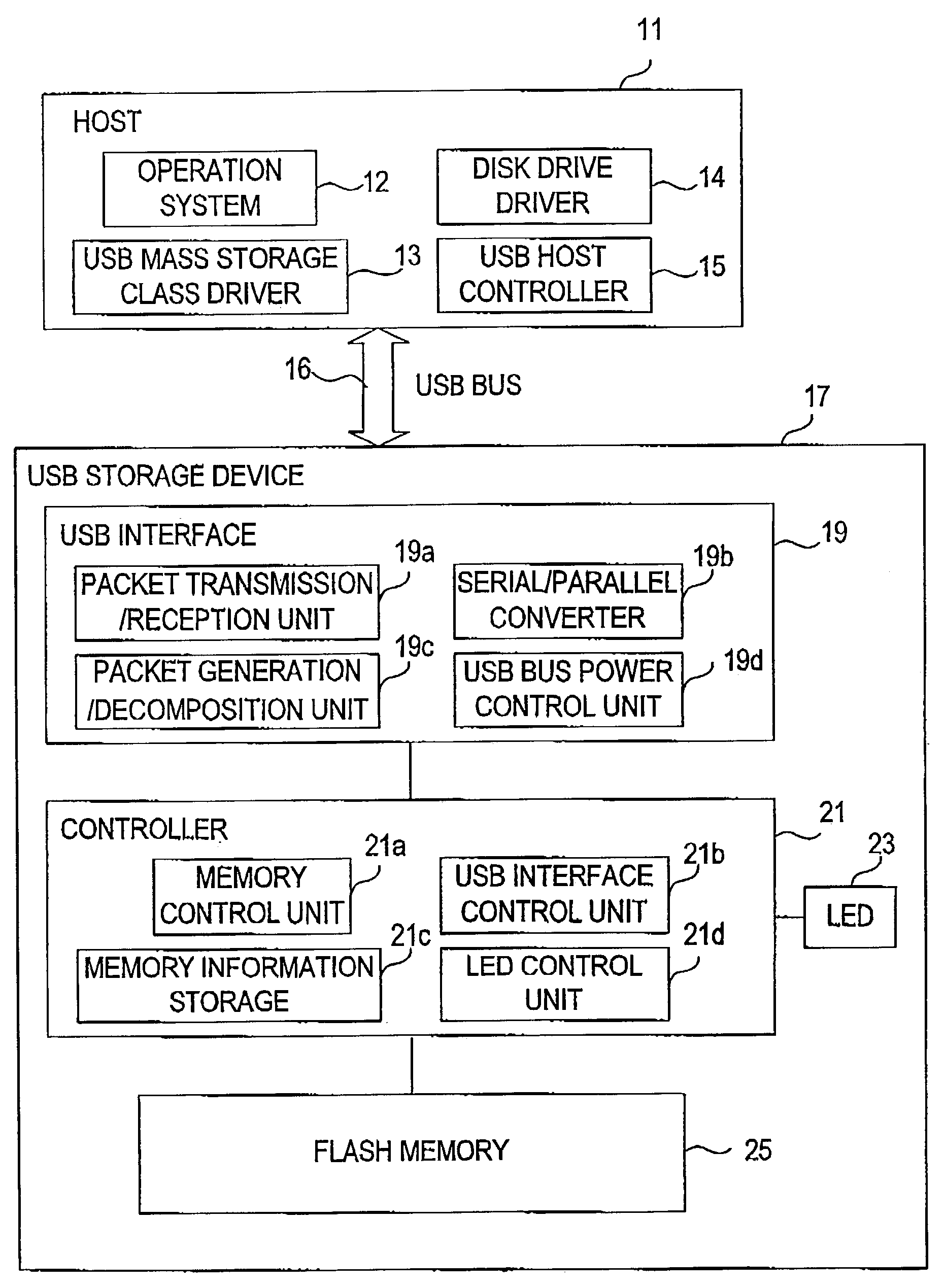
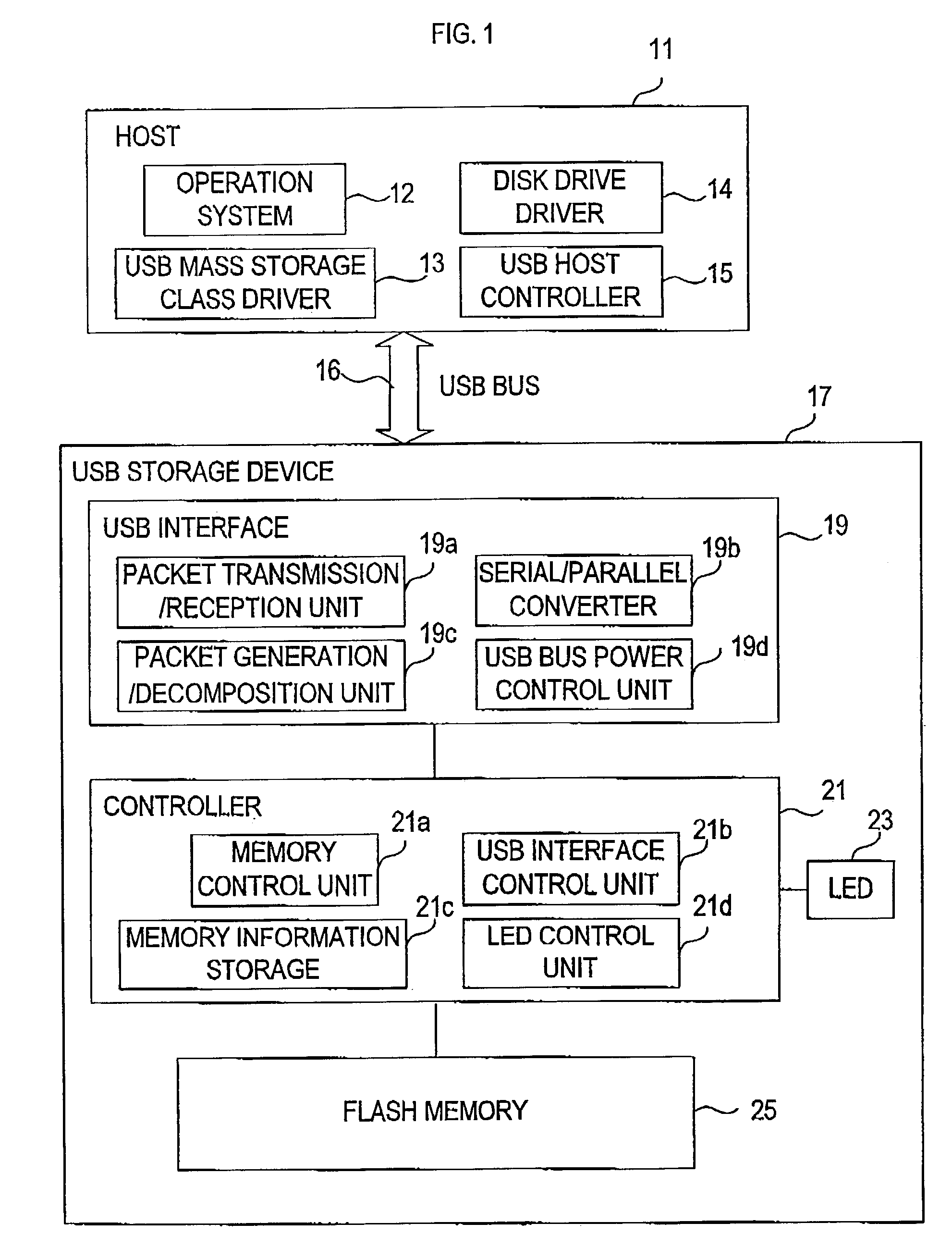
[0039]FIG. 1 is a block diagram showing the schematic structure of a USB storage device 17 according to a first embodiment and a host 11.

[0040](1) Host 11

[0041]A host 11 as an external device is a widely known personal computer, which is provided with at least an operation system 12, a disk drive driver 13 and a USB mass storage class driver 14 as software, and a USB host controller 15 as hardware.

[0042]The operation system 12 is software that comprehensively controls the host 11, such as Windows™ and Mac OS X™. The disk drive driver 13 performs SCSI command conversion of an access command and the like to a storage device received from the operation system 12 and sends the converted command to the USB mass storage class driver 14, as well as receives a command and the like from the USB mass storage class driver 14 and sends the same to the operation system 12. The USB mass storage class driver 14 controls the USB host controller 15. The USB host controller 15 is provided with a...

second embodiment

[0099

[0100]FIG. 7 is a block diagram showing the schematic structure of an ink jet printer 71 according to a second embodiment and a host 11. The ink jet printer 71 corresponds to a USB storage device and the host 11 corresponds to an external device. The same portions or units as in the first embodiment are assigned the same reference numbers to avoid a repeated explanation.

[0101]The ink jet printer 71 is provided with a USB interface 19, a controller 21, a flash memory 25, an MPU 73, a printing head 75 and an actuator 77. The USB interface 19 corresponds to communication means, the controller 21 corresponds to control means, and the flash memory 25 corresponds to storage means. The MPU 73, the printing head 75 and the actuator 77 correspond to printing means.

[0102]The MPU 73 communicates with the host 11 through the USB interface 19 and the controller 21, and controls the operation of the printing head 75 and the actuator 77 based on the information from not shown various sensors....

third embodiment

[0109

[0110]FIG. 8 is a block diagram showing the schematic structure of a scanner 81 according to a third embodiment and a host 11. The scanner 81 corresponds to a USB storage device and the host 11 corresponds to an external device. The same portions or units as in the first embodiment are assigned the same reference numbers to avoid a repeated explanation.

[0111]The scanner 81 is provided with a USB interface 19, a controller 21, a flash memory 25, an MPU 83, a CCD 85 and an actuator 87. The USB interface 19 corresponds to communication means, the controller 21 corresponds to control means, and the flash memory 25 corresponds to storage means. The MPU 83, the CCD 85 and the actuator 87 correspond to scanner means.

[0112]The MPU 83 communicates with the host 11 through the USB interface 19 and the controller 21, and controls the operation of the CCD 85 and the actuator 87. While the controller 21 and the MPU 83 are separately configured in the third embodiment, all or part of their f...


PUM


Abstract

A USB storage device having the function of preventing stored software from being deleted by mistake achieved with as simple a structure as possible. In the USB storage device, the storage area is divided into an area in which execution of reading, writing and deleting is allowed and an area in which only execution of reading is allowed. Information to make a USB mass storage class driver recognize these areas as areas corresponding, respectively, to logical unit numbers defined in the SCSI command set of the USB mass storage class driver owned by the host is stored in the USB storage device. The information includes logical unit numbers, formats, writing / deleting allowed / not allowed flag, logical block numbers and physical block numbers. By this, the USB mass storage class driver recognizes the USB storage device as a SCSI device having two logical units.

Description

BACKGROUND OF THE INVENTION[0001](i) Field of the Invention[0002]The present invention relates to a USB storage device for storing information using a semiconductor memory.[0003](ii) Background Art[0004]These days, attachable and detachable USB storage devices, each of which comprises an installed flash memory and an interface according to the USB (Universal Serial Bus) standard and has a compact configuration by integrating its USB connector portion into the main body, are widely known as described in Publication of Unexamined Japanese Patent Application No. 2000-259275. Such USB storage devices with a compact configuration can be manufactured at a low cost, and are utilized for companies' sales promotion items into which software of commercials and others is written.[0005]Most of these USB storage devices are provided with a physical switch, such as a write protect switch, to prevent the software from being deleted by mistake. By changing the switch, switching between the state in...

Claims


Application Information

Patent Timeline
Patent Type & Authority Patents(United States)
IPC IPC(8): G06F12/00G06F12/14G06F3/06G06F3/08G06F21/00G06K19/07
CPCG06F3/0619G06F3/0644G06F3/0679G06F21/6218G06F3/0655G06F3/0632G06F2221/2153
Inventor OISHI, YUJINAKAMURA, KIMITOSHITOKUNAGA, MEGUMIMIYAZAKI, KAORUITO, KAIHEIFUJITA, NAOKI
Owner HAGIWARA SOLUTIONS CO LTD
Learn More