Touch sensing device

a technology of sensing device and touch, which is applied in the direction of instruments, computing, electric digital data processing, etc., can solve the problems of false detection, increased the need to raise the threshold with increasing the size of the detection electrode, so as to reduce the possibility and simplify the configuration of the controller

Inactive Publication Date: 2016-03-31
HOSIDEN CORP
View PDF1 Cites 0 Cited by
  • Summary
  • Abstract
  • Description
  • Claims
  • Application Information

AI Technical Summary

Benefits of technology

[0011]The touch sensing device in this aspect provides at least the following technical features and effects. First, it is possible for the following reason to reduce the possibility of falsely detecting a conductor other than a detection target even if the detection area of the sensing face is enlarged. In a case where the detection target approaches the detection area, this approach changes an output signal or signals from exactly the predetermined number of detection electrode(s) in the counterpart area corresponding to the detection area. In a case where a conductor of a size different from that of an intended detection target approaches the detection area, this approach changes an output signal or signals from a different number (not the predetermined number, i.e., a number smaller or larger than the predetermined number) of detection electrode(s) in the counterpart area corresponding to the detection area. Accordingly, when judging that the former case applies, the controller can detect that the detection ta...

Problems solved by technology

The enlarged outer shape of the detection electrode allows detection of touch positions of the detection target in a larger detection area but also may cause a false detection.
The controller will detect such an electrostatic capacitance ch...

Method used


Image

  • Touch sensing device
  • Touch sensing device
  • Touch sensing device

Examples


Embodiment Construction

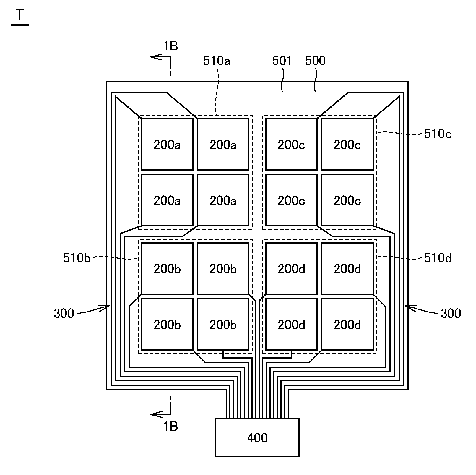
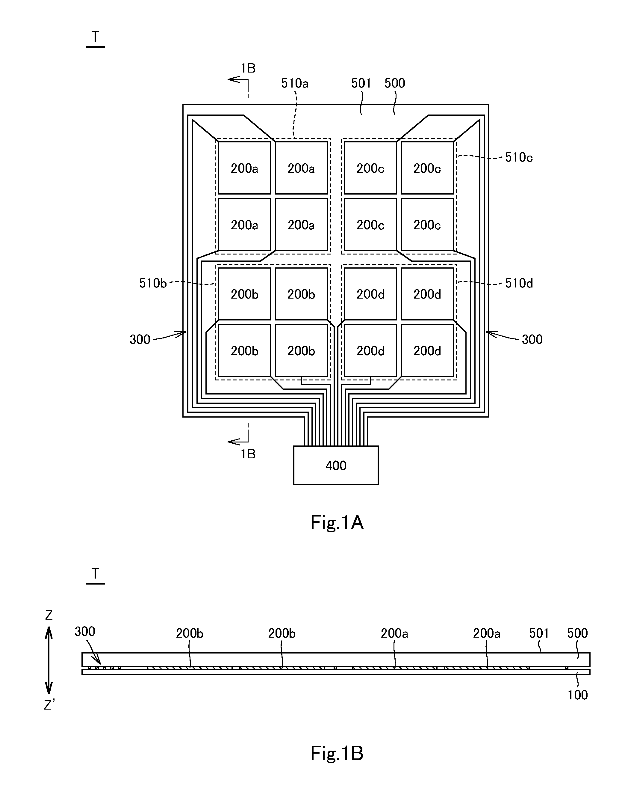
[0023]A touch sensing device T in an embodiment of the invention will be described below with reference to FIG. 1A to FIG. 3B. The touch sensing device T is a self-capacitance touch panel. The touch sensing device T includes a base 100, a plurality of detection electrodes 200a, a plurality of detection electrodes 200b, a plurality of detection electrodes 200c, a plurality of detection electrodes 200d, a plurality of conductive lines 300, a controller 400, and a cover panel 500. These constituents of the touch sensing device T will be described in detail below. The Z-Z′ direction indicated in FIG. 1B is the thickness direction of the touch sensing device T.

[0024]As illustrated in FIGS. 1A and 1B, the cover panel 500 faces the base 100 such as to cover the detection electrodes 200a to 200d and the conductive lines 300. The cover panel 500 may be securely fixed to the base 100 such as to cover the detection electrodes 200a to 200d and the conductive lines 300. The cover panel 500 may b...


PUM


Abstract

A touch sensing device for detecting approach of a detection target to a detection area of a sensing face, including a base, detection electrodes, and a controller. The base includes a counterpart area corresponding to the detection area and being located on a deeper side in the touch sensing device relative to the detection area. The detection electrodes are arranged at intervals in the counterpart area, and an electrostatic capacitance between at least one of the detection electrodes and the detection target changes in response to an approach of the detection target to the detection electrode so as to change an output signal from the detection electrode. The controller detects that the detection target approaches the detection area corresponding to the counterpart area when an output signal or signals from a predetermined number, being at least one, of the detection electrode or electrodes in the counterpart area has changed.

Description

CROSS-REFERENCE TO RELATED APPLICATIONS[0001]The present application claims priority under 35 U.S.C. §119 of Japanese Patent Application No. 2014-195074 filed on Sep. 25, 2014, the disclosure of which is expressly incorporated by reference herein in its entity.BACKGROUND OF THE INVENTION[0002]1. Technical Field[0003]The invention relates to touch sensing devices.[0004]2. Background Art[0005]A conventional touch sensing device is disclosed in Japanese Unexamined Patent Publication No. 2014-071863. This touch sensing device includes a transparent board, a plurality of detection electrodes, and a controller (control circuit). The detection electrodes are provided at intervals on the transparent board. The controller periodically applies a predetermined voltage to the detection electrodes. When a finger (detection target) approaches to any one of the detection electrodes, there is a change in electrostatic capacitance between the detection electrode and the finger. The change in electro...

Claims


Application Information

Patent Timeline
IPC IPC(8): G06F3/044G06F3/041
CPCG06F3/044G06F2203/04101G06F3/0416G06F3/0443
Inventor AO, HITOSHITOYOTA, NAOKI
Owner HOSIDEN CORP
Why Eureka
Try Eureka