
Implantable medical device having flat electrolytic capacitor with differing sized anode and cathode layers

an electrolytic capacitor and flat technology, applied in the field of implantable medical devices, can solve the problems of increasing the cost of high-voltage capacitors, reducing the reliability of capacitors, so as to achieve the effect of maximizing the surface area of anodes electrodes

Inactive Publication Date: 2006-09-19
MEDTRONIC INC
View PDF2 Cites 66 Cited by
  • Summary
  • Abstract
  • Description
  • Claims
  • Application Information

AI Technical Summary

Benefits of technology

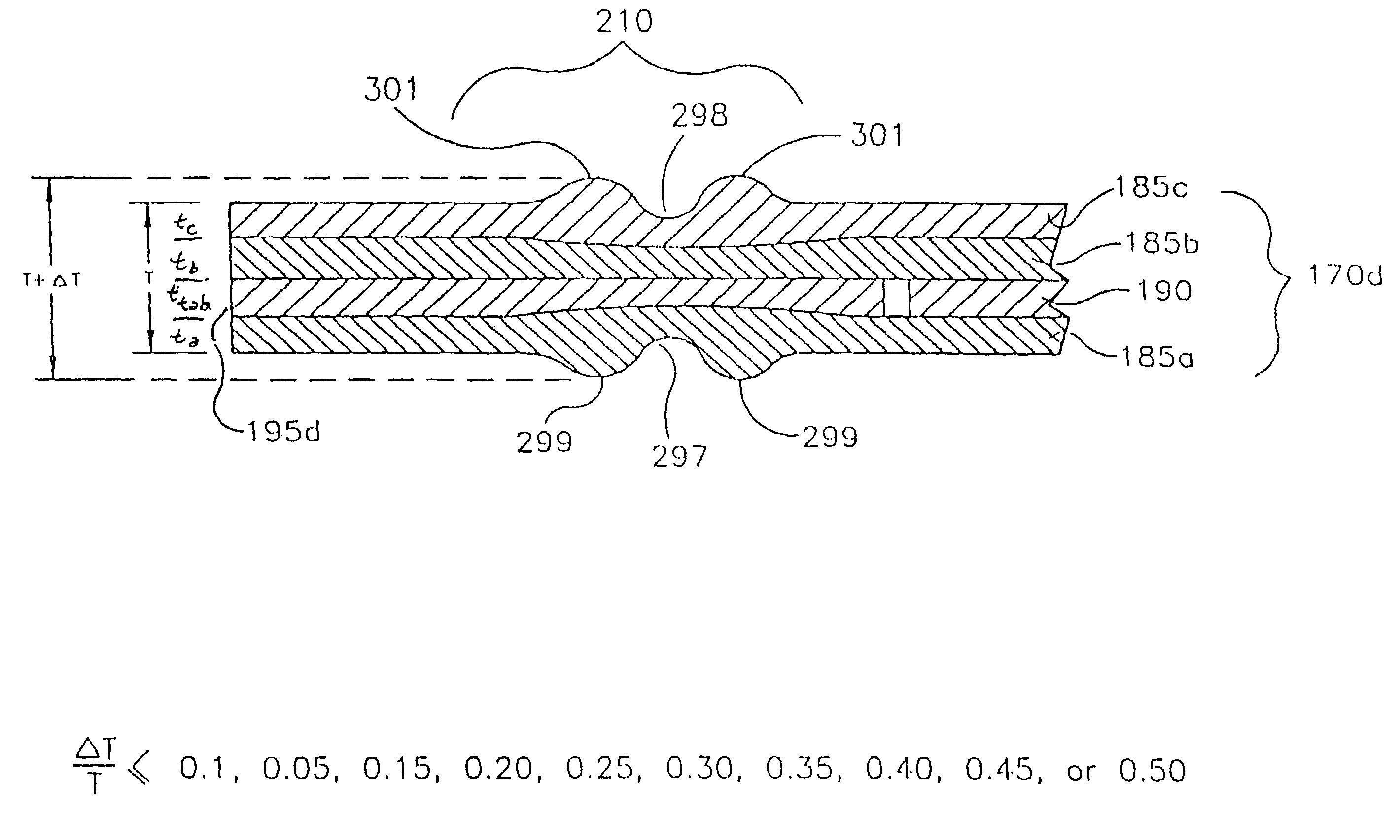
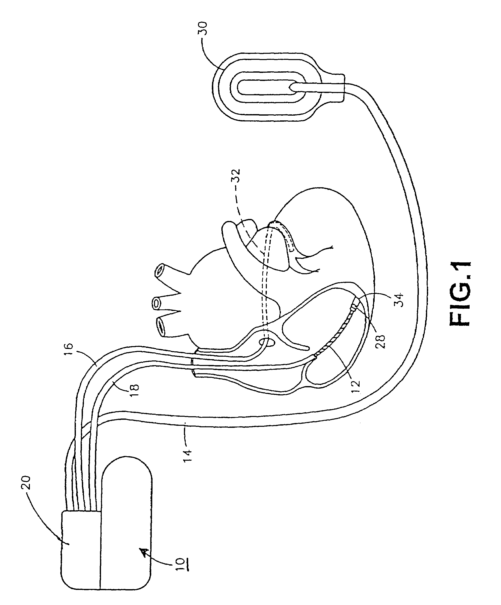
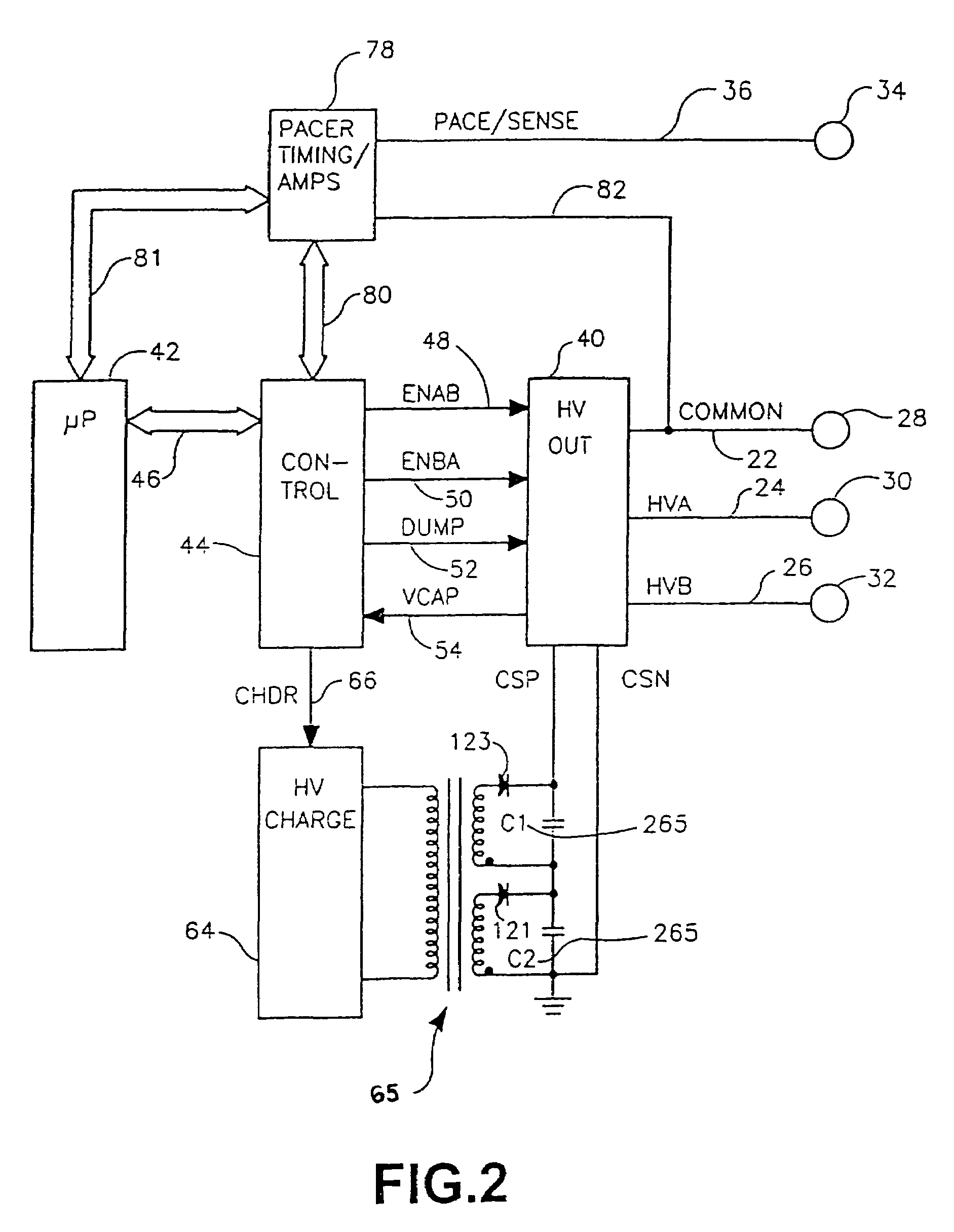
The present invention is about making efficient use of space within the interior case chamber of an electrolytic capacitor, particularly for use in IMDs. The capacitor is formed with an electrode stack assembly comprising a plurality of stacked capacitor layers each comprising an anode sub-assembly of at least one anode layer, a cathode layer, and separator layers wherein the anode and cathode layers have differing dimensions that avoid electrical short circuits between peripheral edges of adjacent anode and cathode layers but maximize anode electrode surface area. The plurality of capacitor layers and further separator layers are stacked into the electrode stack assembly and disposed within the interior case chamber such that the adjacent anode and cathode layers are electrically isolated from one another. The anode layer peripheral edges of the anode subassemblies of the stacked capacitor layers extend closer to the case side wall than the cathode peripheral edges of the cathode layers of the stack of capacitor layers throughout a major portion of the case chamber periphery. The separator layer peripheral edges extend to the case periphery and space the anode layer peripheral edges therefrom. The anode layer surface area is maximized, and short circuiting of the anode layers with the cathode layers is avoided. A case liner can also be disposed around the electrode stack assembly periphery. The technical effects of this invention are efficient use of space within the interior case chamber of an electrolytic capacitor and maximization of anode electrode surface area while avoiding short circuiting of the anode layers with the cathode layers.

Problems solved by technology

Earlier developed automatic implantable defibrillators (AIDs) did not have cardioversion or pacing capabilities.
The battery(s) and high voltage capacitor(s) used to provide and accumulate the energy required for the cardioversion / defibrillation shocks have historically been relatively bulky and expensive.
At the same time, reliability of the capacitors cannot be compromised.
Consequently, these and other components in a capacitor and the desired capacitance limit the extent to which its physical dimensions may be reduced.
The cylindrical shape and paper core of commercial photoflash capacitors limits the volumetric packaging efficiency and thickness of an ICD IPG housing made using same.
Those alignment members necessarily add volume to the capacitor while taking away from the total amount of “active” electrode material available, thereby decreasing the energy density of the capacitor.
This approach is wasteful of space that could be used by anode layers to increase capacity.

Method used


Image

  • Implantable medical device having flat electrolytic capacitor with differing sized anode and cathode layers
  • Implantable medical device having flat electrolytic capacitor with differing sized anode and cathode layers
  • Implantable medical device having flat electrolytic capacitor with differing sized anode and cathode layers

Examples


case liner 300

[0137]Case liner 300 is made of an appropriate thickness of electrically insulating material depending upon the mechanical design of electrode stack assembly 225, the amount of separator layer overhang, the desired distance D1 separation between electrode stack periphery 226 and the case side wall surface 92, etc. In one embodiment liner wall thickness is in the range of 0.001 to 0.100 inches (0.025 to 0.254 mm) and more preferably in the range of 0.003 to 0.005 inches (0.075 to 0.127 mm). Liner wall thickness is also a function of the type of insulating material from which liner 300 is made.

[0138]In one embodiment, liner 300 is made of a polymeric material or polymeric blend of materials, and in one preferred embodiment the polymeric material is polysulfone. Other suitable polymeric materials include polypropylene, polyethylene and ETFE. Optionally, liner 300 can be formed of other insulating materials, such as those materials previously disclosed herein for construction of the wir...


PUM


Abstract

A capacitor is described. The capacitor includes a case chamber. An electrode stack assembly is disposed within the case chamber. The electrode stack assembly includes a layer. The layer includes an anode subassembly. The anode subassembly comprises at least one anode layer that has an anode edge disposed at a first distance from an interior wall of the case chamber. The layer also includes a capacitor layer. The capacitor layer includes a cathode edge disposed at a second distance from the wall interior. The second distance is greater than the first distance.

Description

RELATED APPLICATION[0001]This application is a continuation application of prior U.S. patent application Ser. No. 10 / 918,061, filed Aug. 13, 2004, entitled Implantable Medical Device Having Flat Electrolytic Capacitor with Differing Sized Anode and Cathode Layers”, now U.S. Pat. No. 6,963,482.[0002]This application is a continuation-in-part of U.S. patent application Ser. No. 09 / 531,352 filed Mar. 20, 2000, now U.S. Pat. No. 6,678,559 in the names of Mark D. Breyen et al., and entitled IMPLANTABLE MEDICAL DEVICE HAVING A CAPACITOR ASSEMBLY WITH LINER.FIELD OF THE INVENTION[0003]This invention relates to implantable medical devices (IMDs) and their various components, including flat electrolytic capacitors for same, and methods of making and using same, particularly to an electrode stack assembly comprising a plurality of stacked capacitor layers each comprising an anode sub-assembly of at least one anode layer, a cathode layer and separator layers wherein the anode and cathode layer...

Claims


Application Information

Patent Timeline
Patent Type & Authority Patents(United States)
IPC IPC(8): H01G4/35A61N1/375A61N1/39H01G9/06H01G9/08
CPCA61N1/375A61N1/3956A61N1/3968H01G9/004H01G9/14H01G9/04H01G9/06H01G9/08H01G9/008A61N1/37512
Inventor BREYEN, MARK D.JACOBS, ANDREW MICHAELRORVICK, ANTHONY W.PIGNATO, PAUL A.
Owner MEDTRONIC INC
Learn More