Filter arrangement for balanced and unbalanced line systems

a filter arrangement and line system technology, applied in transmission, multiple-port network, electrical equipment, etc., can solve the problems of large number of unbalanced line systems used in practice, unbalanced circuits, power amplifiers and antennas implemented in an unbalanced technique, etc., to improve resonator filter arrangement, improve resonator filter performance, and high packing density

Inactive Publication Date: 2006-09-19
INFINEON TECH AG
View PDF17 Cites 5 Cited by
  • Summary
  • Abstract
  • Description
  • Claims
  • Application Information

AI Technical Summary

Benefits of technology

[0035]It is an advantage of the present invention, that due to the inventive band-pass filter, which is for example realized as an LDC resonator band-pass filter (LDC=Lumped Distributed Coupled), a high integrated diplexer (frequency separating filter) is realizable, that meets the required properties regarding transmission loss and selection properties including a power compatibility of 36 dBm in the handset device.
[0036]A further advantage of the present invention is that it allows synthesising a band-pass filter that carries out a mode conversion between an unbalanced and a balanced power mode apart from its outstanding selection properties. If this filter is realized with coupled lines in a ceramics a very high packing density is achieved on the one hand due to the low number of line elements and on the other hand due to the fact, that the lines are coupled and therefore lie very close together.
[0037]According to another advantage of the present invention it is possible to clearly improve resonator filters of high quality, like e.g. SAW filters using the inventive topology, so that the number of required resonator is lower with the same blocking isolation and therefore the costs for realization are decreased apart from a simultaneous decrease of transmission losses. If a mode conversion is necessary, no 180° line is necessary any more according to the present invention. The present invention therefore opens the possibility to realize band-pass filters with mode conversion properties using other high grade resonators, like e.g. using crystal resonators and bulk acoustic wave resonators.
[0038]As no additional lines are necessary according to the present invention and as the phase accuracy of a resonator is better than that of a short acoustic line, in principle lower transmission losses result for filters according to the present invention.
[0039]According to another advantage of the present invention a topology for a filter with balanced inputs and outputs is provided.

Problems solved by technology

However, power amplifiers and antennas are implemented in an unbalanced technique.
In the mobile radio area unbalanced circuits, like e.g. diplexers, are the conventional and only used circuits so far.
Further, a large number of line systems used in practice are unbalanced systems, like e.g. coaxial, microstrip and strip lines.
The above described, known filter realizations are disadvantageous in so far, that they are exclusively available for balanced line systems or exclusively for unbalanced line systems.
Thus, the filter realizations either comprise a balanced input gate and a balanced output gate or an unbalanced input gate and an unbalanced output gate.
The drawback of the above-described realizations of band-pass filters known in the art is on the one hand, that band-pass filters having discrete inductive devices and capacitors for commercial microwave products produced in large amounts are of no interest, as the number of required devices is very high and therefore the required area is very large.
Further, the losses in the passband are intolerably high.
Further, SAW filters are not large-signal stable, so that the signal output by a power amplifier would destroy the filter.
After the output of the transmit / receive circuit a SAW filter is too expensive.
A balanced transformer has too little selection properties compared to a SAW filter, so that its use is not advantageous either.
Regarding the realizations for band-pass filters known in the art it can be summarised, that they are too expensive to realize, comprise a too high loss in the passband and / or a too low selection property.

Method used


Image

  • Filter arrangement for balanced and unbalanced line systems
  • Filter arrangement for balanced and unbalanced line systems
  • Filter arrangement for balanced and unbalanced line systems

Examples


Embodiment Construction

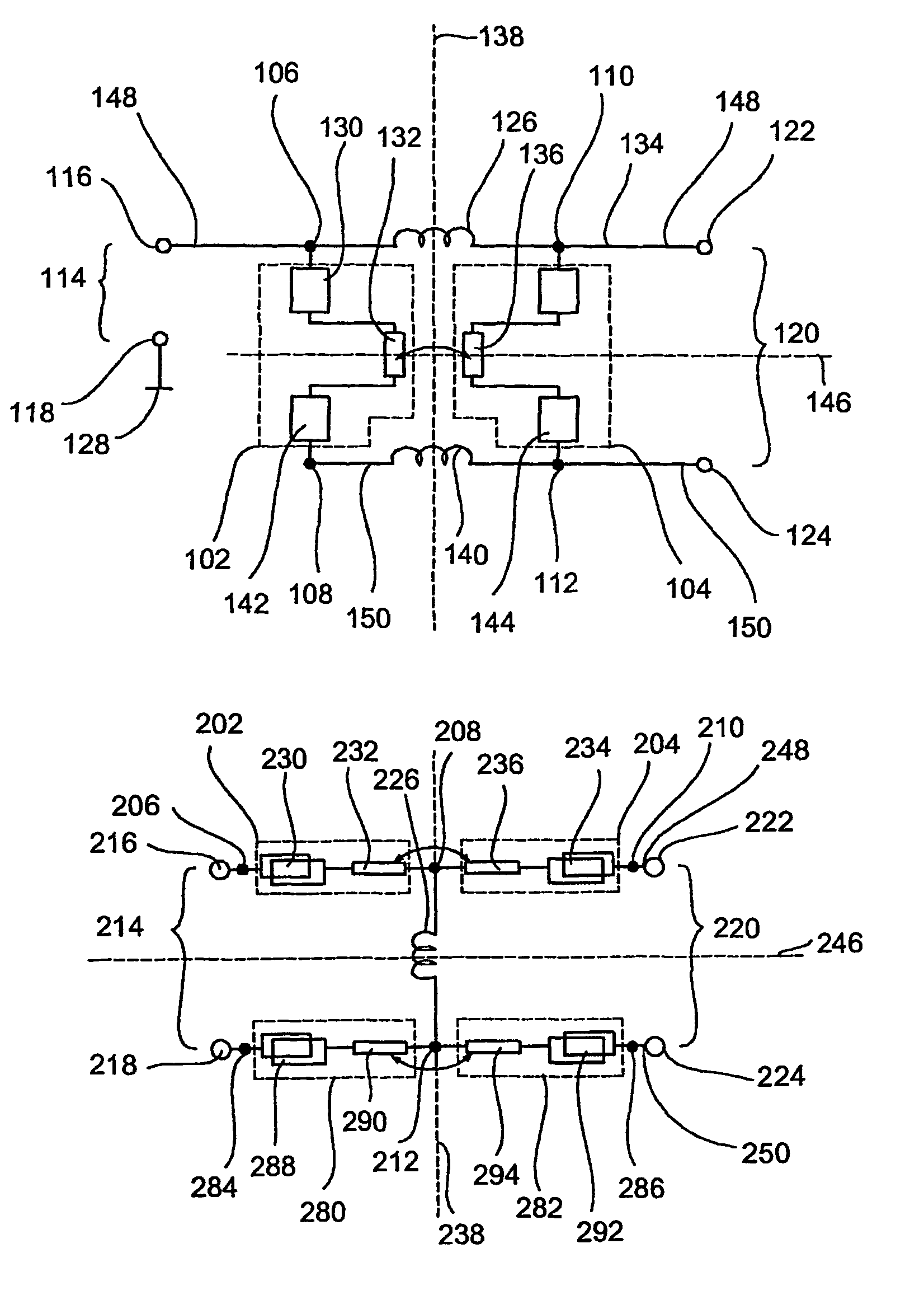
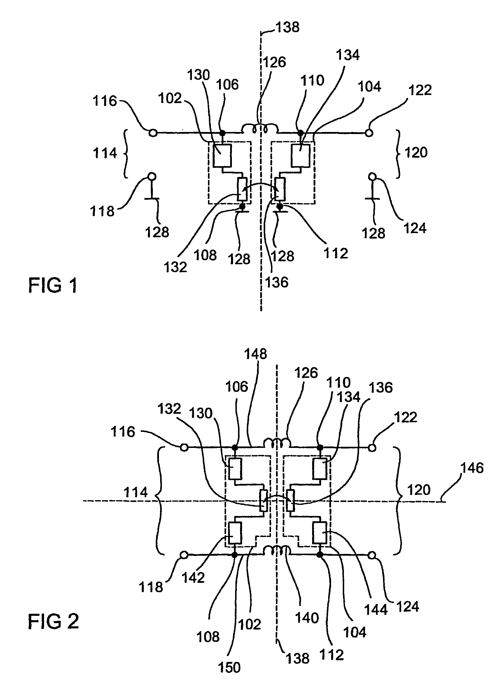
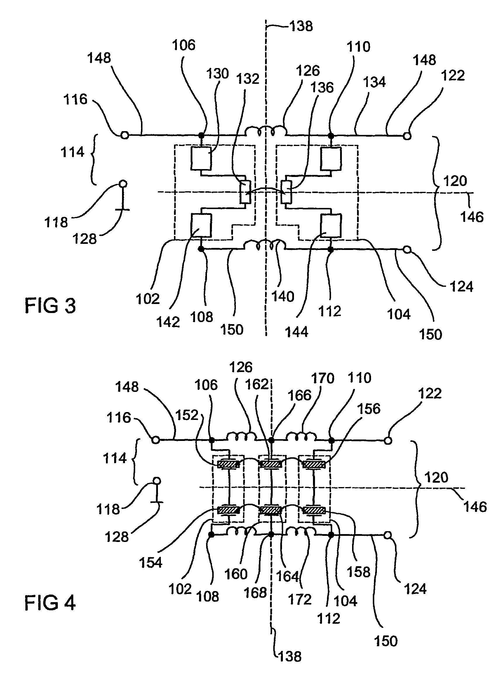
[0051]FIG. 1 shows a resonator band-pass filter according to a first embodiment of the present invention with an unbalanced input and output. The resonator band-pass filter includes a first resonator circuit 102 and a second resonator circuit 104. The first resonator circuit 102 is connected between a first node 106 and a second node 108. The second resonator circuit 104 is connected between a third node 110 and a fourth node 112. The resonator band-pass filter further includes an input port 114 including a first input port node 116 and a second input port node 118. Further, an output port 120 is provided including a first output port node 122 and a second output port node 124. Further, the resonator band-pass filter includes an inductive device 126, e.g. in the form of a coil, connected between the first node 106 and the third node 110.

[0052]In the embodiment shown in FIG. 1 the first input port node 116 is connected to the first node 106 and the first output port node 122 is conne...


PUM


Abstract

A filter arrangement includes one first resonator circuit connected between a first node and a second node. A second resonator circuit is connected between a third node and a fourth node. The first resonator circuit and the second resonator circuit are intercoupled. Further, an inductive device is provided, connected between the first node and the third node.

Description

BACKGROUND OF THE INVENTION[0001]1. Field of the Invention[0002]The present invention relates to a filter arragement and in particular to a resonator band-pass filter arrangement for balanced and unbalanced line systems.[0003]2. Description of the Prior Art[0004]Band-pass filters are needed in almost any microwave application. In particular narrow-band transmit / receive circuits (so called transceiver-circuits), as they are used in mobile radio communication systems, need band-pass filters in order to suppress all interference signals from outside the used frequency band. Thus, large interference signals cannot limit the receiver and small interference signals do not deteriorate the basic noise. Further, band-pass filters are used in so-called mutiband systems in order to select the individual bands over frequency-separating filters, so-called diplexers.[0005]Good band-pass filters distinguish themselves by showing very little electrical losses in the passband and having as much isol...

Claims


Application Information

Patent Timeline
Patent Type & Authority Patents(United States)
IPC IPC(8): H03H9/54H01P1/20H03H9/64H03H7/07H03H7/09H03H7/42H03H9/00
CPCH03H7/42H03H9/0095H03H9/0028H03H7/09H03H7/1708H03H7/425
Inventor HEUERMANN, HOLGERRUEDIGER, JENS
Owner INFINEON TECH AG
Why Eureka
Try Eureka