
Method and apparatus for C-plane volume compound imaging

a compound imaging and c-plane technology, applied in the field of diagnostic ultrasound systems, can solve the problems of longer exam time, difficult to correctly identify a specific plane of data within, etc., and achieve the effect of improving imag

Active Publication Date: 2006-09-19
GE MEDICAL SYST GLOBAL TECH CO LLC
View PDF15 Cites 8 Cited by
  • Summary
  • Abstract
  • Description
  • Claims
  • Application Information

AI Technical Summary

Benefits of technology

"The patent describes a method and system for displaying an enhanced image of data collected from an ultrasound scan. The system acquires a volume data set and defines a C-plane or B-mode image based on the data. The system then processes a portion of the data based on the defined image and creates an enhanced image that is displayed. The technical effect of this patent is to provide a better image quality and more accurate data analysis for ultrasound scans."

Problems solved by technology

Unfortunately, it has been difficult to correctly identify a specific plane of data within the volume of data that a user wishes to see.
Unfortunately, this is time consuming and may result in longer exam times to acquire and process additional data, and may perhaps require additional volumes of data to be acquired or an exam to be repeated.

Method used


Image

  • Method and apparatus for C-plane volume compound imaging
  • Method and apparatus for C-plane volume compound imaging
  • Method and apparatus for C-plane volume compound imaging

Examples


Embodiment Construction

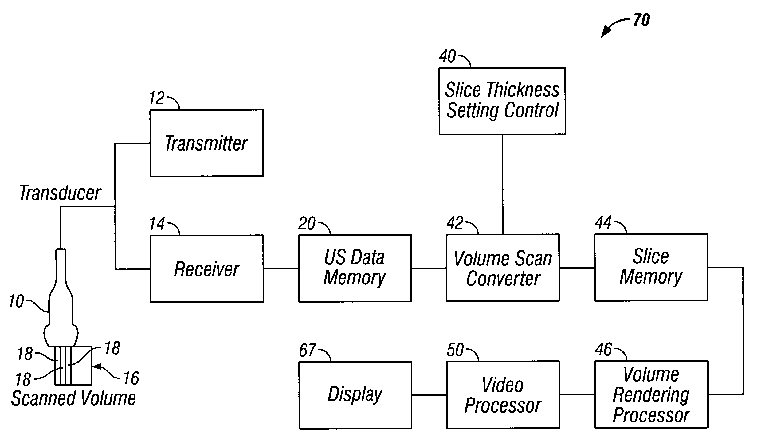
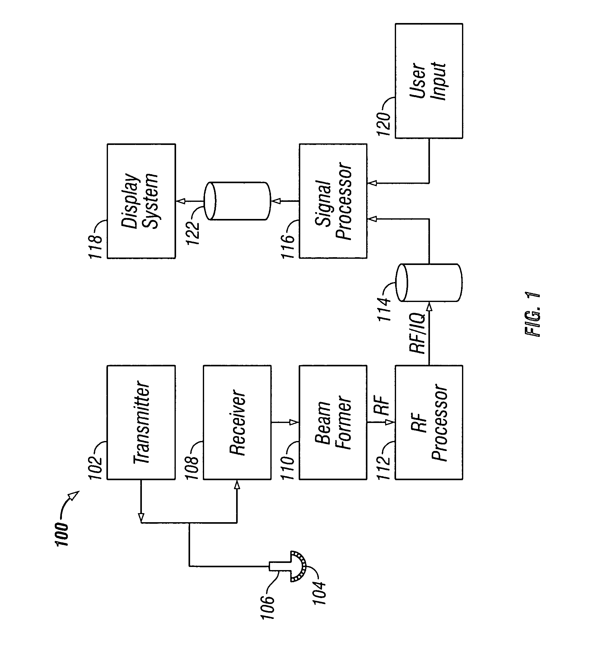
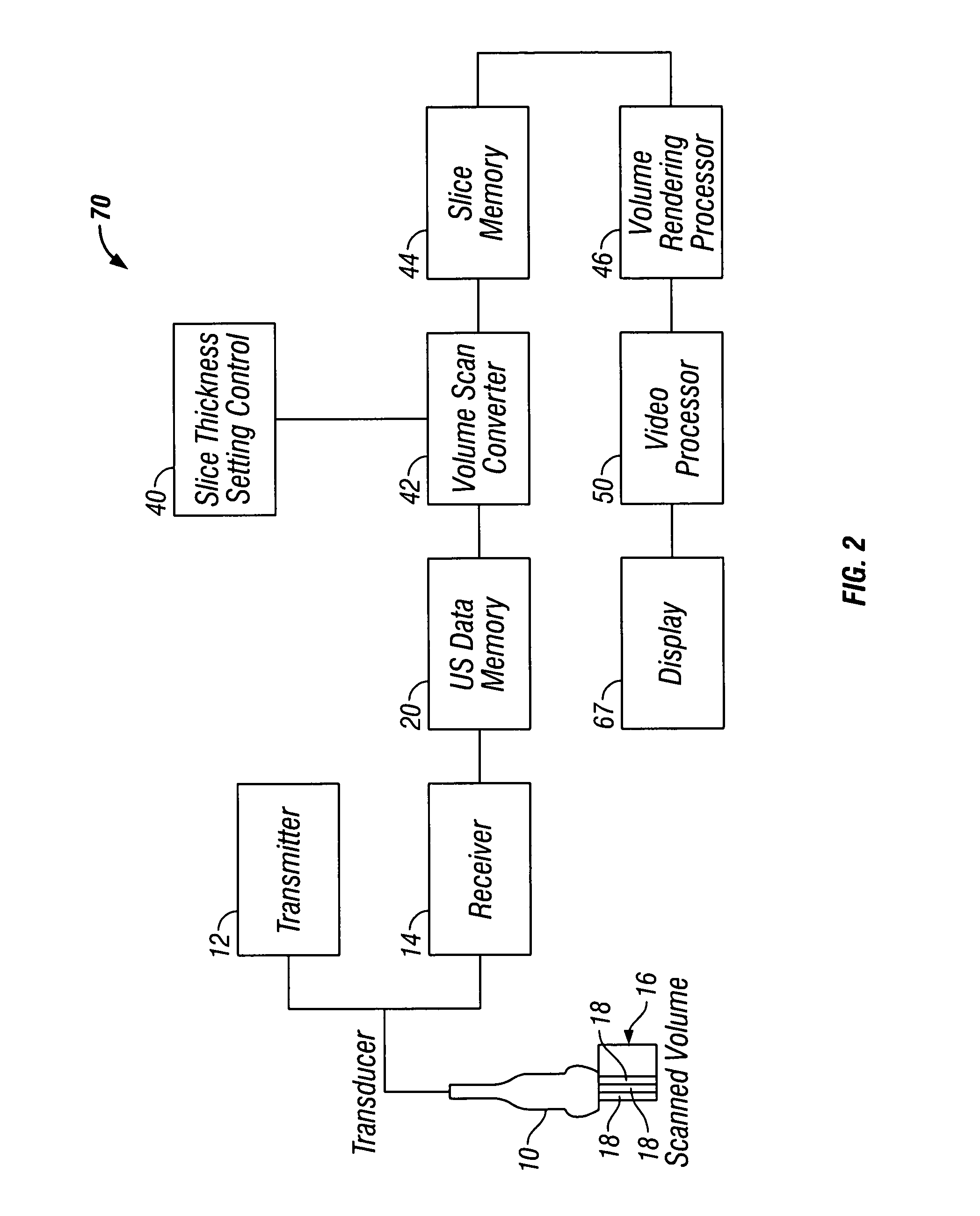
[0016]FIG. 1 illustrates a block diagram of an ultrasound system 100 formed in accordance with an embodiment of the present invention. The ultrasound system 100 includes a transmitter 102 which drives transducers 104 within a transducer 106 to emit pulsed ultrasonic signals into a body. A variety of geometries may be used. The ultrasonic signals are back-scattered from structures in the body, like blood cells or muscular tissue, to produce echoes which return to the transducer elements 104. The echoes are received by a receiver 108. The received echoes are passed through a beamformer 110, which performs beamforming and outputs an RF signal. The RF signal then passes through an RF processor 112. Alternatively, the RF processor 112 may include a complex demodulator (not shown) that demodulates the RF signal to form IQ data pairs representative of the echo signals. The RF or IQ signal data may then be routed directly to RF / IQ buffer 114 for temporary storage. A user input 120 may be us...


PUM


Abstract

Method and apparatus for displaying an enhanced image based on an image plane of data. A volume data set is acquired, and a plane is defined on an image based on the volume data set. The plane may be a C-plane. Data within the volume data set which is defined by the plane is processed with an image enhancing technique and the resultant enhanced image is displayed.

Description

BACKGROUND OF THE INVENTION[0001]This invention relates generally to diagnostic ultrasound systems. In particular, the present invention relates to method and apparatus for processing and displaying an enhanced image based on an identified plane within a volume of data.[0002]Conventional ultrasound scanners are capable of acquiring and displaying a volume of data. Unfortunately, it has been difficult to correctly identify a specific plane of data within the volume of data that a user wishes to see. It has been necessary in conventional ultrasound scanners to store the volume of data prior to processing in order to locate the desired anatomic data. Unfortunately, this is time consuming and may result in longer exam times to acquire and process additional data, and may perhaps require additional volumes of data to be acquired or an exam to be repeated.[0003]Additionally, there is a need to correlate the resultant processed image with its location within the volume of data. It may be d...

Claims


Application Information

Patent Timeline
Patent Type & Authority Patents(United States)
IPC IPC(8): A61B8/00A61B8/14G01S7/52G01S15/89G06T5/00G06T15/08
CPCA61B8/14A61B8/483G01S7/52046G01S7/52061G06T5/008G01S15/8993G06T2207/30004Y10S128/916G06T2207/10136G06T5/94
Inventor BRANDL, HELMUTDEISCHINGER, HARALD
Owner GE MEDICAL SYST GLOBAL TECH CO LLC
Learn More