
Continuously variable transmission

Inactive Publication Date: 2006-09-19
NSK LTD
View PDF20 Cites 29 Cited by
  • Summary
  • Abstract
  • Description
  • Claims
  • Application Information

AI Technical Summary

Benefits of technology

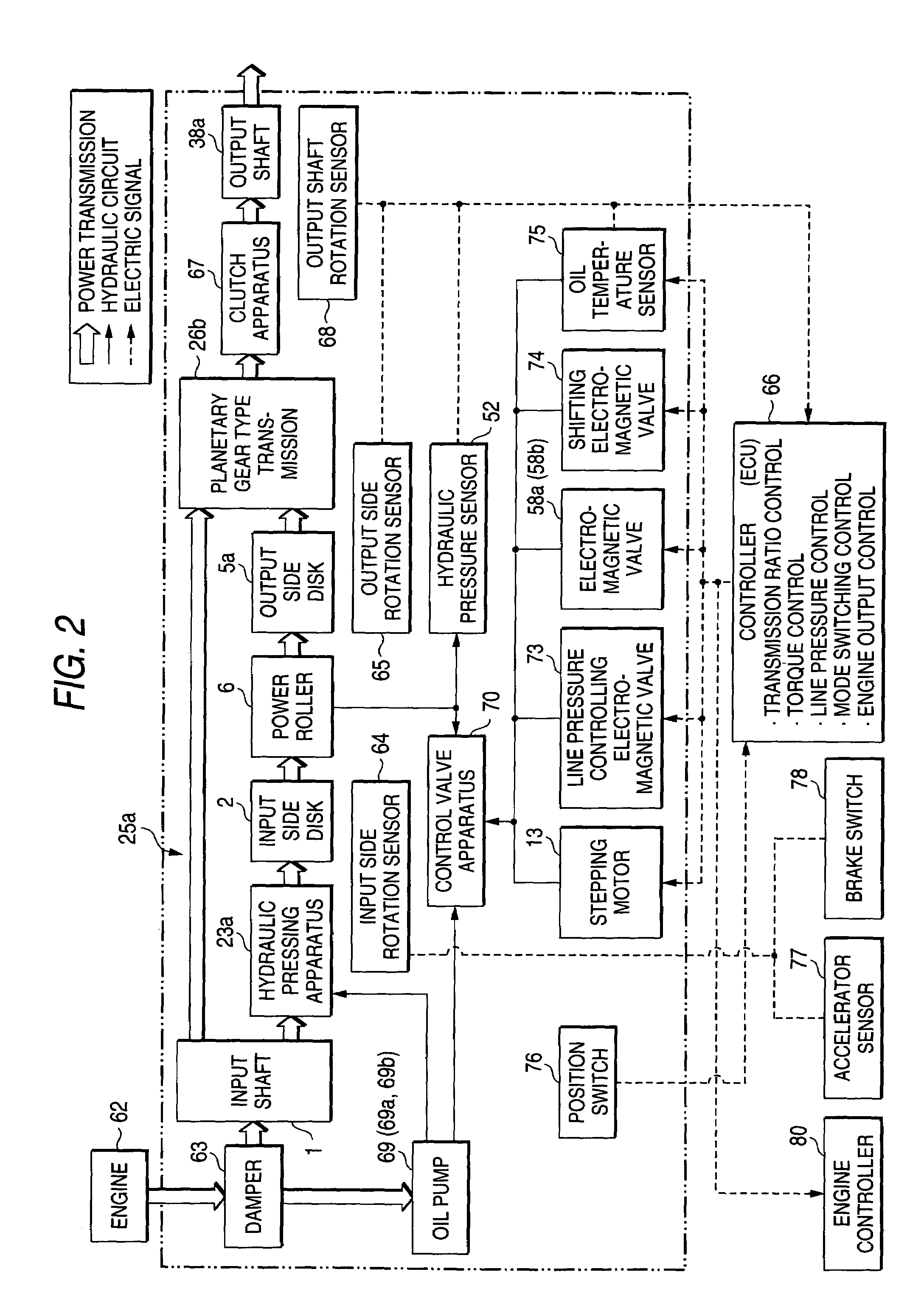
[0073]Therefore, in the case of the invention, the transmission ratio of the toroidal type continuously variable transmission is calculated from the rotational speed of the input side disk and the rotational speed of the output side disk. Therefore, the actual transmission ratio of the toroidal type continuously variable transmission can accurately be calculated regardless of dimensional accuracies and integrating accuracies of a number of parts constituting the toroidal type continuously variable transmission. Further, when the vehicle is not run, the actuator integrated to the toroidal type continuously variable transmission is displaced while calculating the accurate transmission ratio, and the torque applied to the output shaft is converged to null or a small value when needed. Therefore, a speed at which the output shaft starts rotating at an instance of switching from the state in which the vehicle is not run to the state of running the vehicle and a torque applied to the output shaft as necessary can strictly be controlled regardless of the individual difference of the toroidal type continuously variable transmission.

Problems solved by technology

Therefore, when the transmission ratio control of the toroidal type continuously variable transmission 25 is not carried out strictly, there is a possibility that a strange feeling is given to a driver or the driver is difficult to carry out driving operation.
Conversely, when the transmission ratio control of the toroidal type continuously variable transmission 25 is not carried out strictly in starting and the torque applied to the output shaft 38 becomes excessively small, there is a possibility that smooth starting is not carried out or a vehicle is moved rearward in starting on an uphill.
However, in the case of the structure as disclosed in JP-A-10-103461, the control is carried out only by the pressure difference and therefore, it is difficult to stop an attitude of the trunnion at an instance at which the passing torque coincides with the target value.
Therefore, an allowable range capable of controlling the speed ratio stays in a range in which unreasonable force is not exerted to the control portion and is limited in comparison of the case of running at a low speed.

Method used


Image

  • Continuously variable transmission
  • Continuously variable transmission
  • Continuously variable transmission

Examples


Embodiment Construction

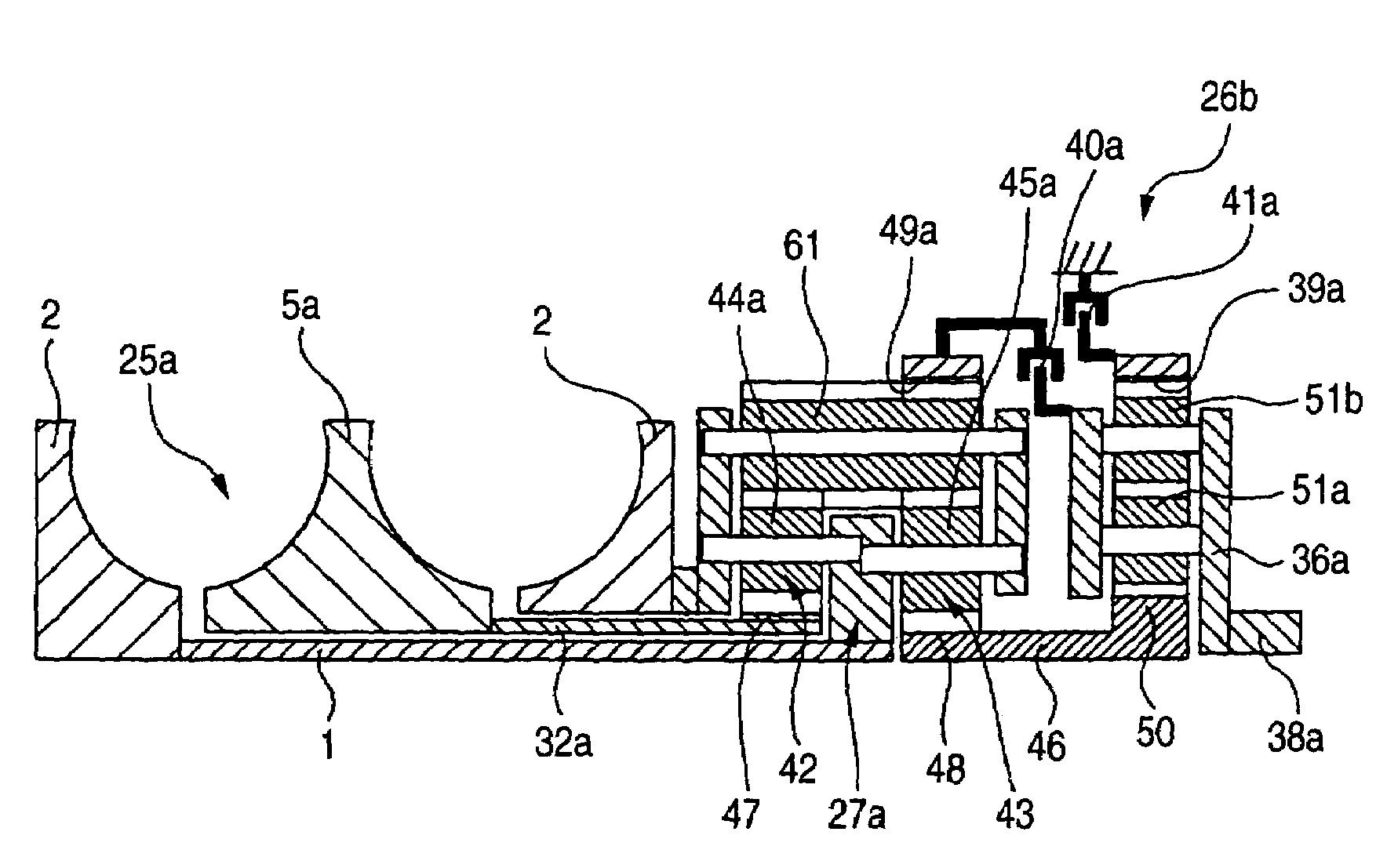
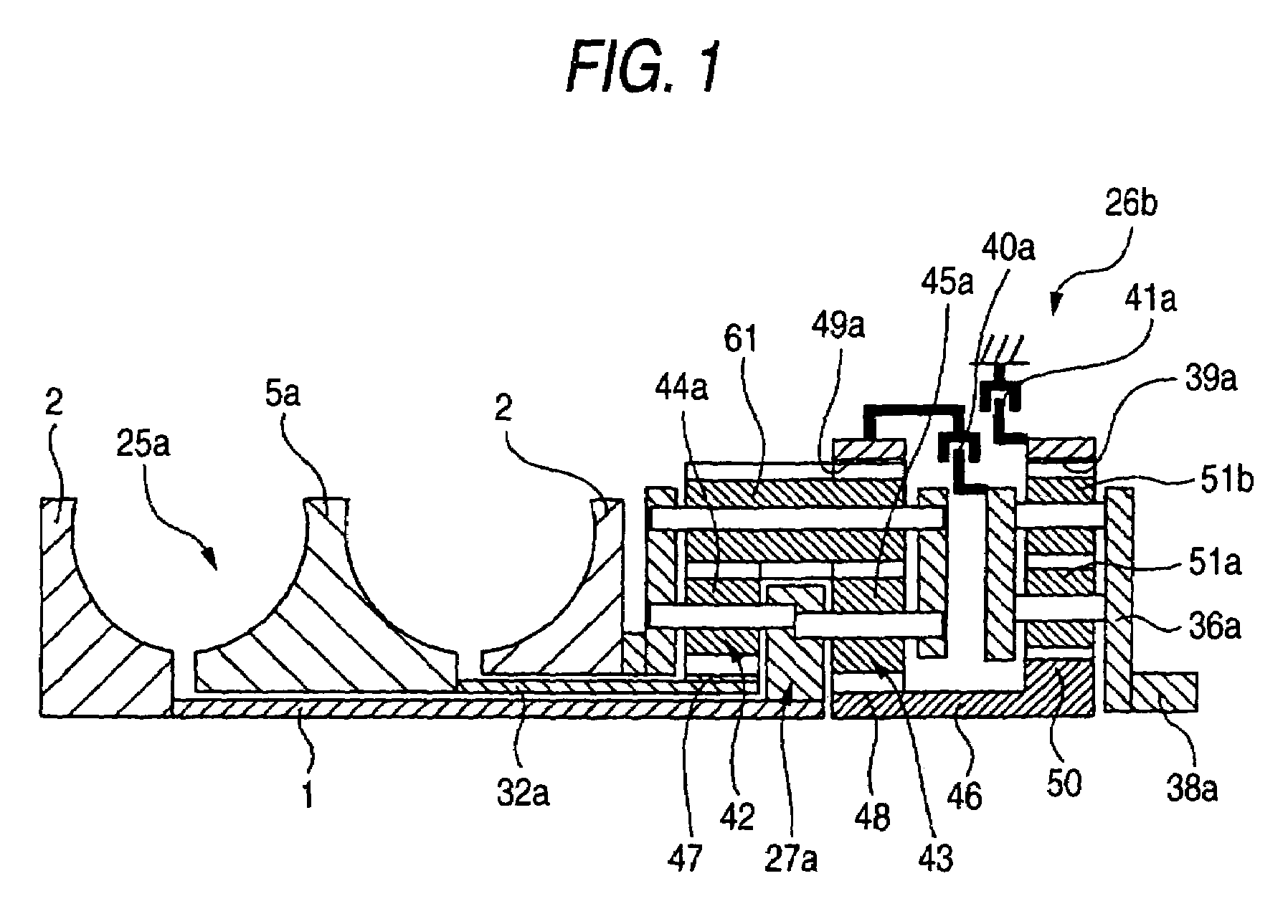
[0088]FIGS. 1 through 3 show a first example of an embodiment of the invention. FIG. 1 shows an example of a continuously variable transmission apparatus constituted by combining a toroidal type continuously variable transmission 25a and a planetary gear type transmission 26b constituting a differential unit. The constitution of the continuously variable transmission apparatus is basically similar to the continuously variable transmission apparatus of the prior art shown in FIG. 9 or of the structure shown in FIG. 10, mentioned above. Particularly, in the case of the continuously variable transmission apparatus of the example, among respective planetary gear elements constituting the first and the second planetary gears 42, 43 of the planetary gear type transmission 26b, there is used a planetary gear element 61 provided on an outer side in a diameter direction which is prolonged in an axial direction. Further, the planetary gear element 61 is brought in mesh with the respective pla...


PUM


Abstract

A rotational speed of an input side disk is detected by an input side rotation sensor, and a rotational speed of an output side disk is detected by an output side rotation sensor, respectively. Based on detected values of the two sensors, a transmission ratio of a toroidal type continuously variable transmission is calculated. Further, a rotational speed of the output shaft is calculated from the transmission ratio and a gear ratio of a planetary gear type transmission. In a state in which the select lever selects no-running condition, the transmission ratio of the toroidal type continuously variable transmission is controlled such that the rotational speed of the output shaft becomes null or at an extremely low speed even when the running state is selected at the instance. Further, a position of a control valve apparatus under the state is stored to a controller.

Description

BACKGROUND OF THE INVENTION[0001]The present invention relates to a continuously variable transmission apparatus utilized as an automatic transmission apparatus for a vehicle integrated with a toroidal type continuously variable transmission, for improving a characteristic when the vehicle is stationary or at an extremely low speed.[0002]A toroidal type continuously variable transmission, as shown in FIGS. 6 to 8, has been researched to use as an automatic transmission apparatus for a vehicle, and is partially embodied. The toroidal type continuously variable transmission is referred to as a double cavity type, and input side disks 2, 2 are supported by surroundings of both end portions of an input shaft 1 via ball splines 3, 3. Therefore, the two input side disks 2, 2 are supported concentrically and synchronizingly rotatably. Further, an output gear 4 is supported at a surrounding of a middle portion of the input shaft 1 rotatably relative to the input shaft 1. Further, output sid...

Claims


Application Information

Patent Timeline
IPC IPC(8): B60W10/10F16H37/02F16H37/08F16H59/10F16H59/40F16H59/42F16H59/70F16H61/00F16H61/02F16H61/66F16H61/662F16H61/664
CPCF16H61/6648F16H37/086Y10T477/6217Y10T477/619F16H2037/0886
Inventor INOUE, EIJIIMANISHI, TAKASHI
Owner NSK LTD
Learn More