Illumination compensator for curved surface lithography

a curved surface, lithography technology, applied in the direction of microlithography exposure apparatus, printers, instruments, etc., can solve the problems of incoherent illumination, lens cannot transmit higher-order frequencies, and the image quality of aerial images begins to suffer, so as to achieve effective coupling

Inactive Publication Date: 2006-09-12
ANVIK CORP
View PDF6 Cites 3 Cited by
  • Summary
  • Abstract
  • Description
  • Claims
  • Application Information

AI Technical Summary

Benefits of technology

[0010]This invention provides to a large-area lithography system the capability of patterning onto a curved substrate, using a curved mask in order to achieve a fixed track length for conjugate object and image points, by linearly moving a 1:1 projection lens for compensation on a small-field seamless scanning platform, thereby maintaining the curved substrate surface within its depth-of-focus, and by providing an effective coupling of the illumination beam from the curved mask to the projection lens, thereby preserving the partial coherence factor and the related resolution characteristics.
[0012]The object of the invention is to make possible a high-resolution projection imaging operation on a curved substrate with topographical variations significantly greater than the depth-of-focus of the imaging optics.
[0014]Another innovative feature of the invention is to provide, a unique design for zero-power meniscus lens pair by means of a symmetric arrangement of two identical meniscus optical elements so that it works as a null compensator for collimated or converging beams interacting with a curved mask and thus causing negligible deviation or shift of the beam passing through such a device.
[0015]An advantage of such unique configuration for zero-power meniscus lens pair is that the design could be scaled up to conduct large-area curved patterning with relatively smaller cross-section of scanning convergent beam imaging on one of its outer surfaces thus facilitating large-area seamless scanning for curved—curved lithography.

Problems solved by technology

Aerial image quality begins to suffer when the projection lens can no longer transmit the higher-order frequencies.
Though incoherent illumination provides twice the resolution as that of coherent illumination, higher spatial frequencies suffer from lower contrast in the projected image under incoherent illumination.
On the other hand, a curved mask surface can significantly distort the transmitting illuminating beam, depending on the structure of the mask device, causing sever image anomalies and loss of resolution.
It is, however, hard to realize such a meniscus optical element with negligible thickness capable of transmitting UV radiation.
This is very undesirable for scanning systems such as seamless scanning technique because the beam or the ray excurses nonuniformly over the second surface.
Hence, a single meniscus element would not serve the required purpose of an illumination compensator for curved masks in making the beam transmit without deviation or shift.

Method used


Image

  • Illumination compensator for curved surface lithography
  • Illumination compensator for curved surface lithography
  • Illumination compensator for curved surface lithography

Examples


Embodiment Construction

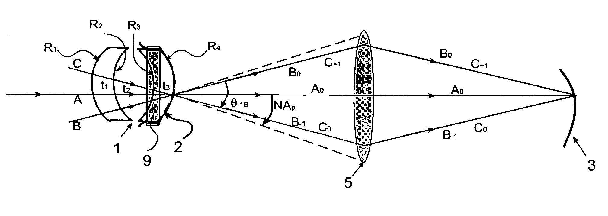
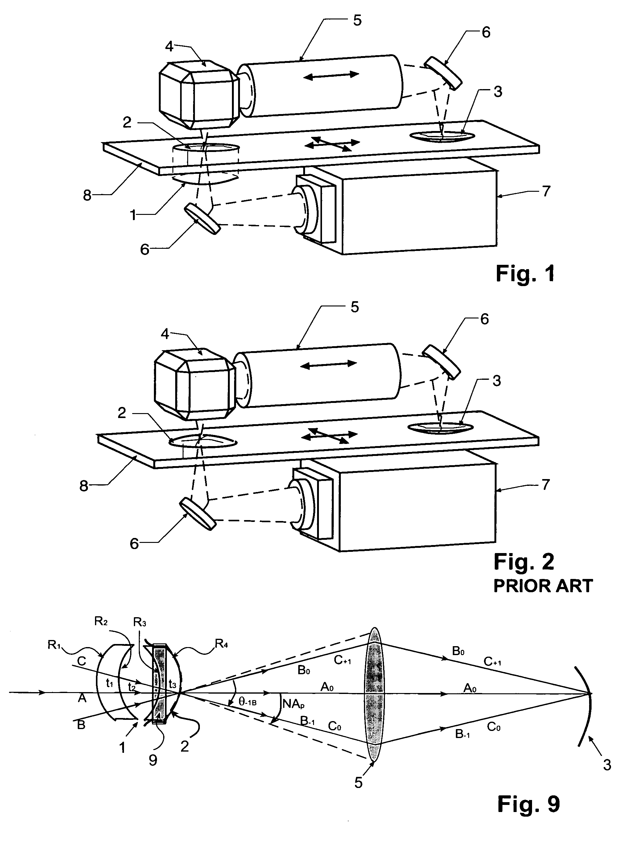
[0026]FIG. 1 and FIG. 2 show the preferred embodiment for patterning onto curved substrates by using a zero-power meniscus lens pair 1, mask 2 having a curvature that is identical to that of the substrate 3 (i.e., the size and shape of the mask 2 and substrate 3 are the same) by additionally performing the imaging using a 1:1 projection imaging system featuring reverser 4, projection lens 5, and fold mirrors 6 as required in directing the patterning beam from illumination source 7 to substrate 3. Stage 8 provides scanning motion. All elements of FIG. 2 (PRIOR ART) are also present in FIG. 1. The difference between the system of FIG. 1 and the PRIOR ART system of FIG. 2 is the presence of the zero-power meniscus lens pair 1, in FIG. 1 and the absence of the zero-power meniscus lens pair 1, in FIG. 2. The zero-power men iscus lens pair 1, in FIG. 1 provides an effective beam coupling between the curved mask and the projection lens.

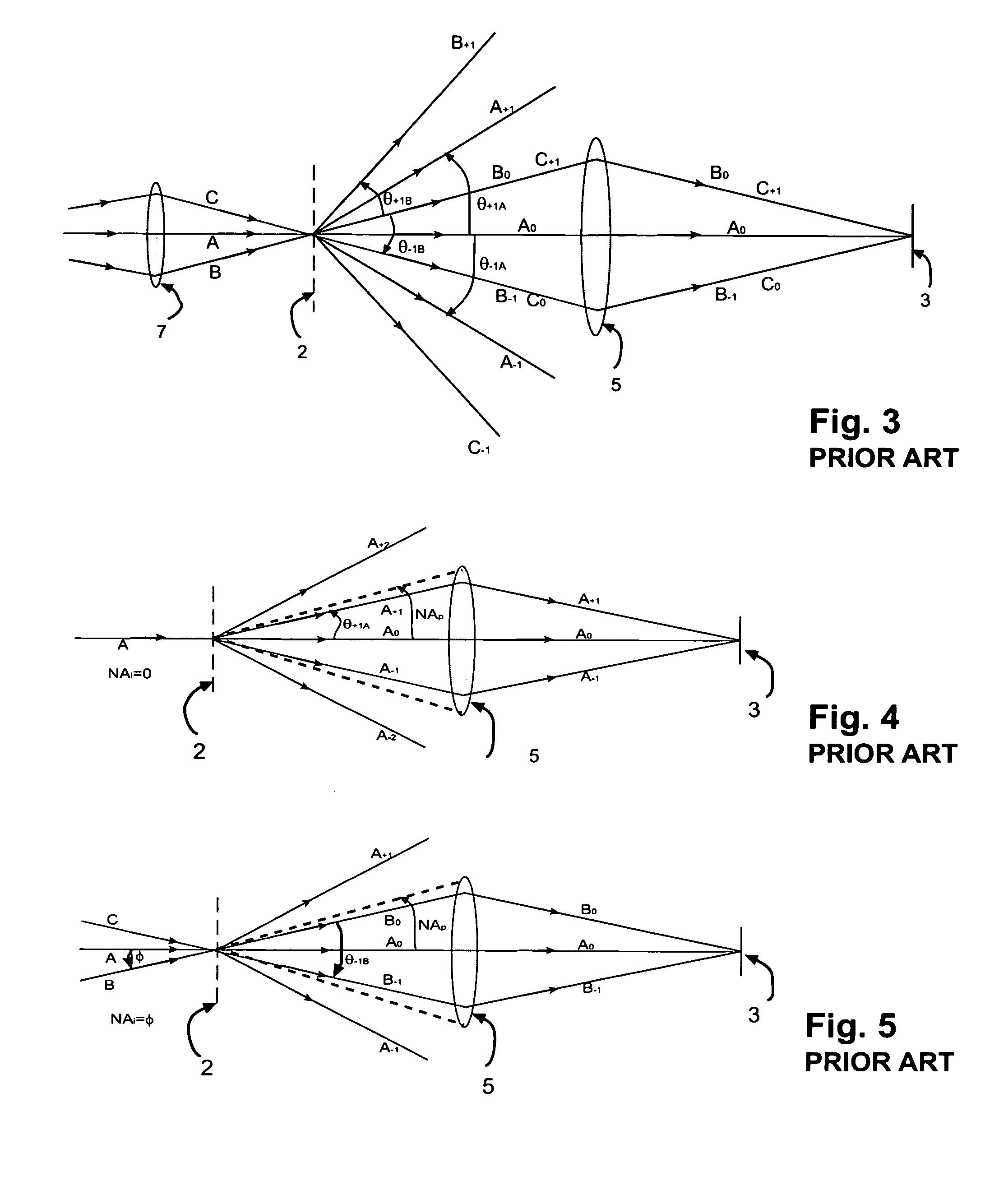
[0027]We hereby discuss the basis of our invention, in...


PUM

PropertyMeasurementUnit
thicknessaaaaaaaaaa
sizeaaaaaaaaaa
shapeaaaaaaaaaa

Abstract

A zero power identical pair of oppositely-oriented meniscus lens elements mounted in the projection light path, serves as curved mask support while compensating for optical anomalies such as beam shift and beam deviations produced by other transparent supports for the curved mask. The zero-power meniscus lens pair, without affecting the transmission beam characteristics, lets the beam diffract as efficiently as does a regular planar mask, thus preserving the partial coherence effects and resolution concepts of projection lithography. This simple but novel optics device is not only expected to clear several barriers for curved mask projection lithography but also find place in other applications where collimated or converging light beams have to travel extra paths without significant aberration.

Description

CROSS-REFERENCE TO RELATED APPLICATIONS[0001](Not Applicable)STATEMENT REGARDING FEDERALLY SPONSORED RESEARCH OR DEVELOPMENT[0002](Not Applicable)REFERENCE TO A MICROFICHE APPENDIX[0003](Not Applicable)BACKGROUND OF THE INVENTION[0004](1) Field of the Invention[0005]This invention relates to projection lithography systems for imaging onto curved substrates, and more particularly relates to a large-area lithography system featuring a curved mask that is identical in size and shape to the curved substrate. An axially moving 1:1 projection lens achieves a constant optical path length for conjugate image points in order to maintain the substrate surface within the depth-of-focus, thereby providing an effective depth-of-focus much larger than the depth-of-focus of the projection optics itself. This invention is centered around a novel illumination compensator which we call ‘Zerogon’, that is part of an illumination system and protects the converging illumination beam from various image a...

Claims


Application Information

Patent Timeline
Patent Type & Authority Patents(United States)
IPC IPC(8): G03B27/68G03B27/42G03B27/58G03F7/20
CPCG03F7/703G03B27/58
Inventor KUCHIBHOTLA, SIVARAMA K.JAIN, KANTIKLOSNER, MARC A.
Owner ANVIK CORP
Why Eureka
Try Eureka