Motor driving apparatus
a technology for motors and motor stops, applied in the direction of motor/generator/converter stoppers, dynamo-electric converter control, dc motor stoppers, etc., can solve the problems of large amount of electric power energy consumed wastefully as heat energy, and the operator's safety is significantly impaired, so as to avoid maintenance work risk and improve efficiency
- Summary
- Abstract
- Description
- Claims
- Application Information
AI Technical Summary
Benefits of technology
Problems solved by technology
Method used
Image
Examples
first embodiment
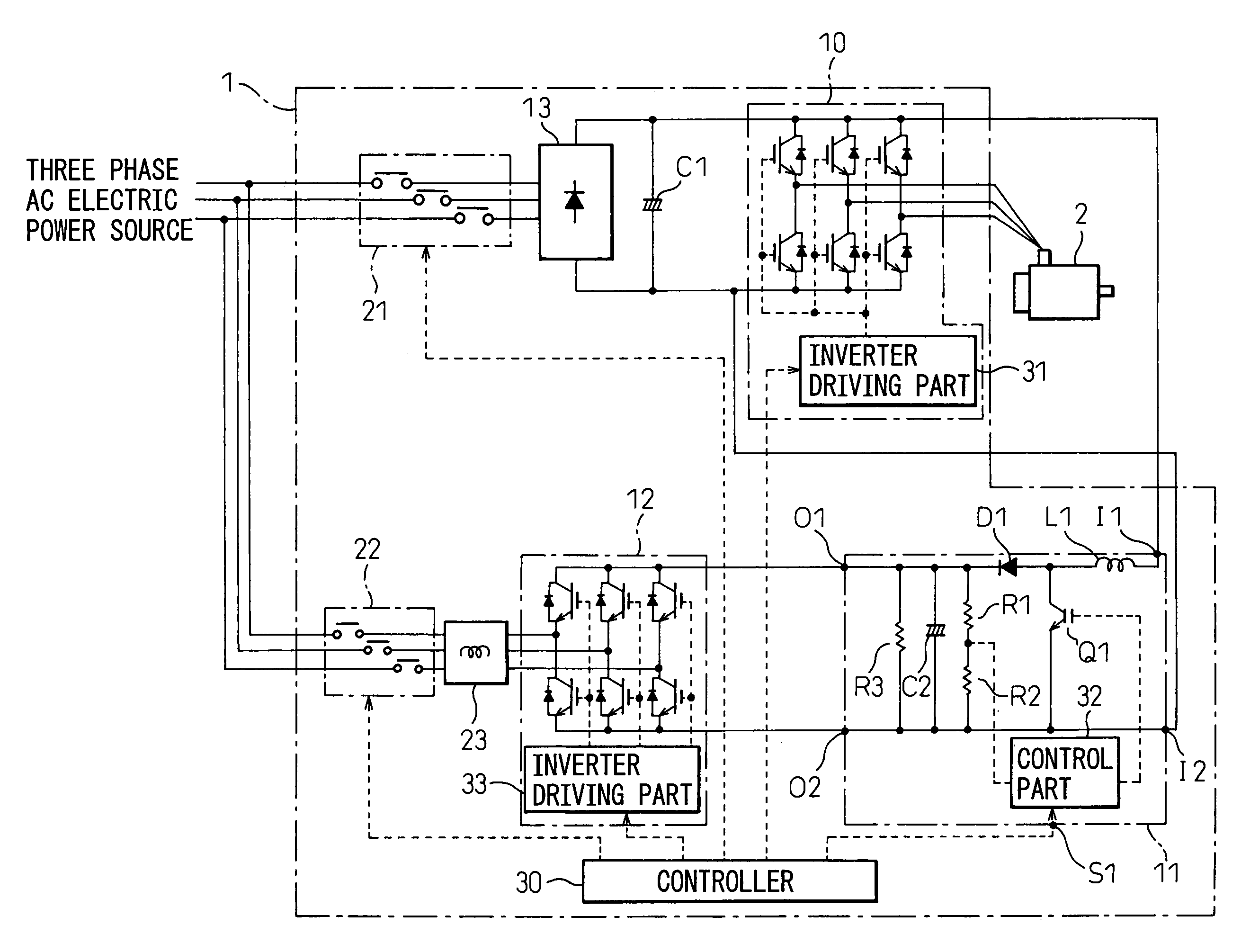
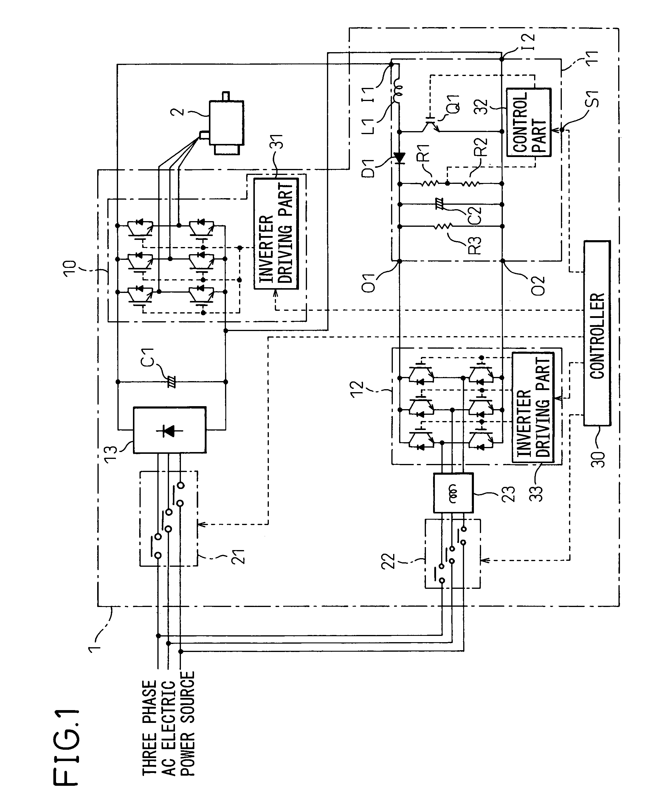
[0022]Hereinafter, preferred embodiments of the present invention will be described in detail with reference to the accompanying drawings. FIG. 1 is a block diagram of a motor driving apparatus of the present invention. In the circuit block diagrams shown in FIGS. 1 and 3 to 5, electric power lines for supplying electric power to drive a motor are designated by solid lines, whereas control lines such as signal lines are designated by dotted lines.
[0023]As shown in the figures, a motor driving apparatus 1 includes a power source rectifier circuit 13 for converting AC electric power supplied from a three-phase AC power source into DC electric power, and an inverter circuit 10 for converting this DC electric power into AC electric power of variable voltage and variable frequency to be supplied to the motor 2, wherein the power source rectifier circuit 13 is connected with the inverter circuit 10 via a DC link.
[0024]The power source rectifier circuit 13 may be constituted, for example, ...
second embodiment
[0044]FIG. 3 is a block diagram of a motor driving apparatus according to the present invention. The exemplary motor driving apparatus 1 shown in FIG. 3 includes a converter circuit 14 that acts as a power source rectifier circuit to perform regeneration. Then, the DC link is provided between the converter circuit 14 and the inverter circuit 10 to transfer the DC electric power, rectified from the three-phase AC electric power by the converter circuit 14, to the inverter circuit 10.
[0045]The converter circuit 14 is constituted by a bridge circuit including power devices (such as transistors, for example) and diodes connected in anti-parallel with these power devices. Then, during normal power operation of the motor 2, the diodes perform full-wave rectification of AC electric power supplied from the three-phase AC power source to convert it into DC electric power.
[0046]On the other hand, during regeneration of the motor 2, when the link voltage divided by the resistors R7 and R8 exce...
third embodiment
[0050]FIG. 4 is a block diagram of a motor driving apparatus according to the present invention. As shown in FIG. 4, the motor driving apparatus 1 includes the converter circuit 14 shown in FIG. 3 that is configured to perform regeneration, the inverter circuit 10 that converts DC electric power into AC electric power and supplies it to the motor 2, and the DC link that connects the converter circuit 14 with the inverter circuit 10 and, similarly to that shown in FIG. 1, the motor driving apparatus 1 is provided with the step-up type DC / DC converter circuit 11, the AC inverter circuit 12, the electromagnetic connector 21 for connecting / disconnecting AC main input, and the electromagnetic connector 22 for connecting / disconnecting AC input to the regeneration inverter.
[0051]The step-up type DC / DC converter circuit 11, the input terminals of which are connected to the DC link, boosts the DC link voltage as described above and outputs it to the AC inverter circuit 12. Then, the AC inver...
PUM
 Abstract
Description
Claims
Application Information
 - R&D
- Intellectual Property
- Life Sciences
- Materials
- Tech Scout
- Unparalleled Data Quality
- Higher Quality Content
- 60% Fewer Hallucinations
Browse by: Latest US Patents, China's latest patents, Technical Efficacy Thesaurus, Application Domain, Technology Topic, Popular Technical Reports.
© 2025 PatSnap. All rights reserved.Legal|Privacy policy|Modern Slavery Act Transparency Statement|Sitemap|About US| Contact US: help@patsnap.com


