
Brake actuator indicator

a technology of brake actuator and indicator, which is applied in the direction of mechanical equipment, brake types, etc., can solve the problems of inability to complete the task, excessive time-consuming procedures, etc., and achieve the effect of simple and effective indicator of the travel of the brake actuator, simple and effective use, and light weigh

Active Publication Date: 2006-09-12
PENNSY CORP
View PDF13 Cites 8 Cited by
  • Summary
  • Abstract
  • Description
  • Claims
  • Application Information

AI Technical Summary

Benefits of technology

[0003]The present invention provides a simple and effective indicator of actuator travel which is adapted for use with conventional air brake-type actuators of the air bag or bellows-type without modification of existing equipment. The indicator device is simple to use, is light in weight yet durable and inexpensive. It is adapted to be fixed in position relative to the actuator in a matter of a few minutes time without the need for tools. If damaged, the indicator can be removed and replaced simply and quickly. An indication that the actuator travel is within acceptable limits can be easily determined without the need of a tape measure or other measuring instruments. In its preferred form, the indicator device comprises a molded plate-like member having fixed indicator marks which comprise the side edges of a cut out or window which is positioned relative to the movable end section of the actuator. So long as the measuring plate on the movable end of the actuator is within the confines of the indicator marks, the inspector knows that actuator travel is within acceptable tolerances.

Problems solved by technology

This has proven to be an unduly time consuming procedure when a long string of rail cars needs to be checked, and in practice, the task is too often simply not done.

Method used


Image

  • Brake actuator indicator
  • Brake actuator indicator
  • Brake actuator indicator

Examples


Embodiment Construction

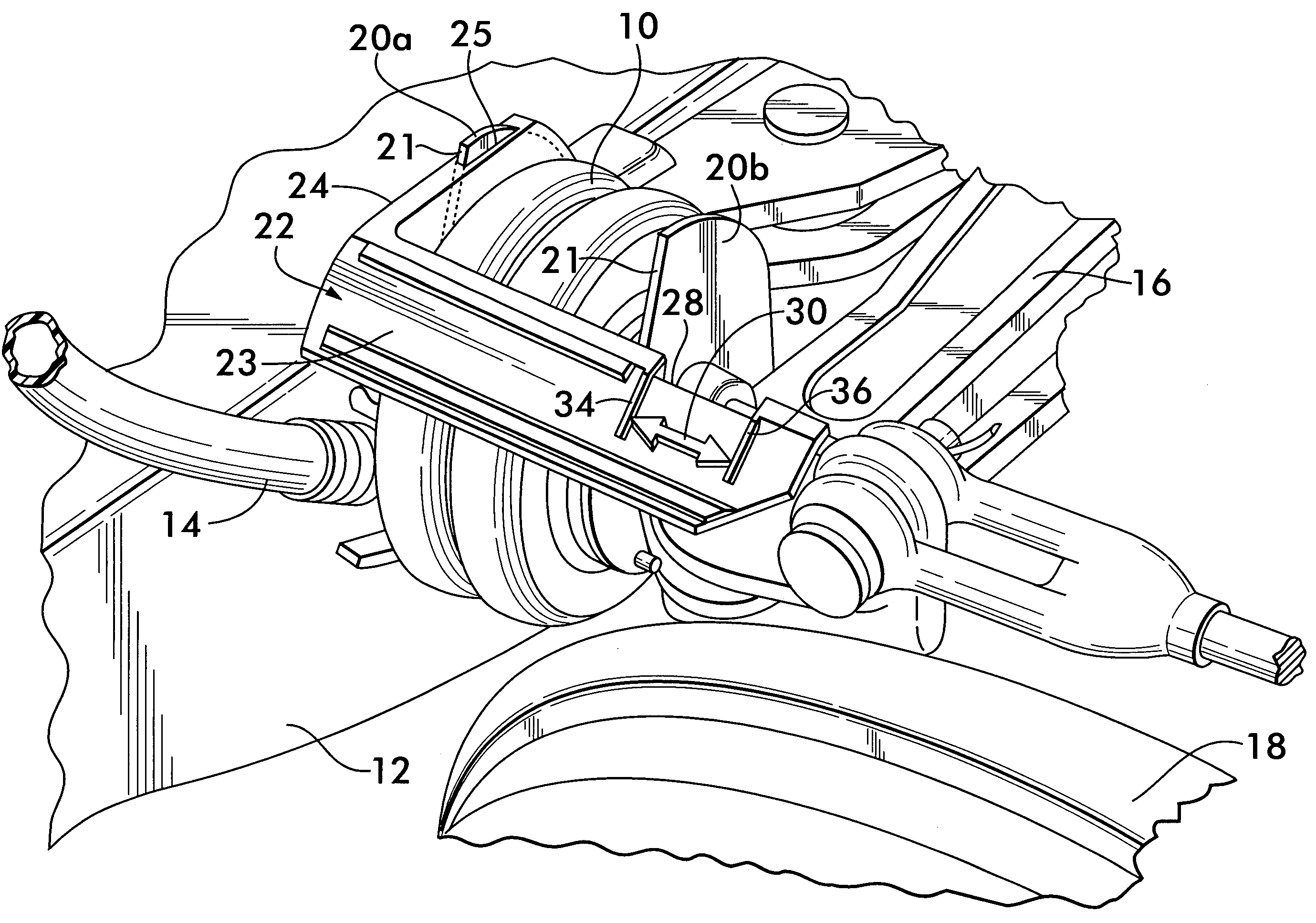
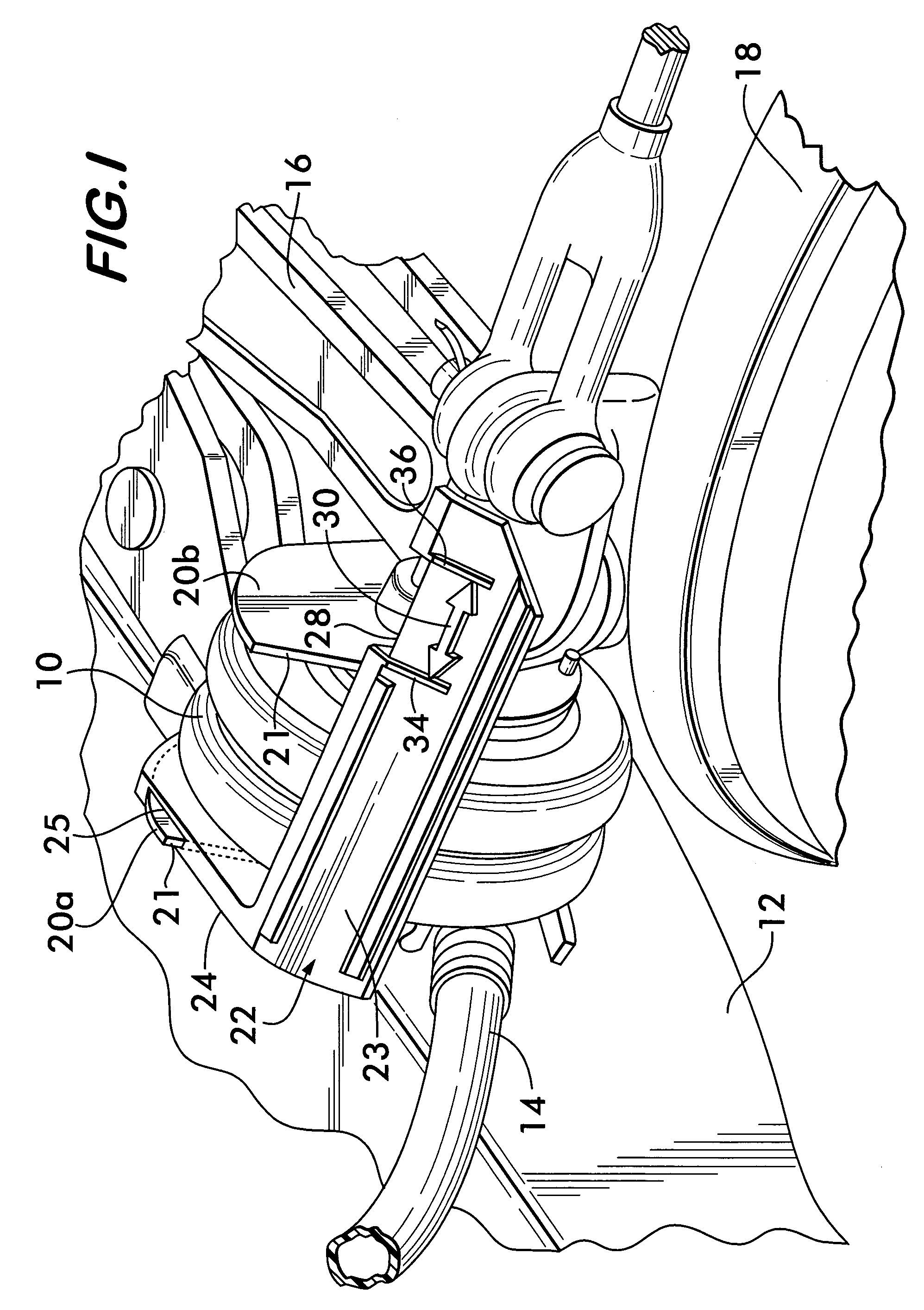
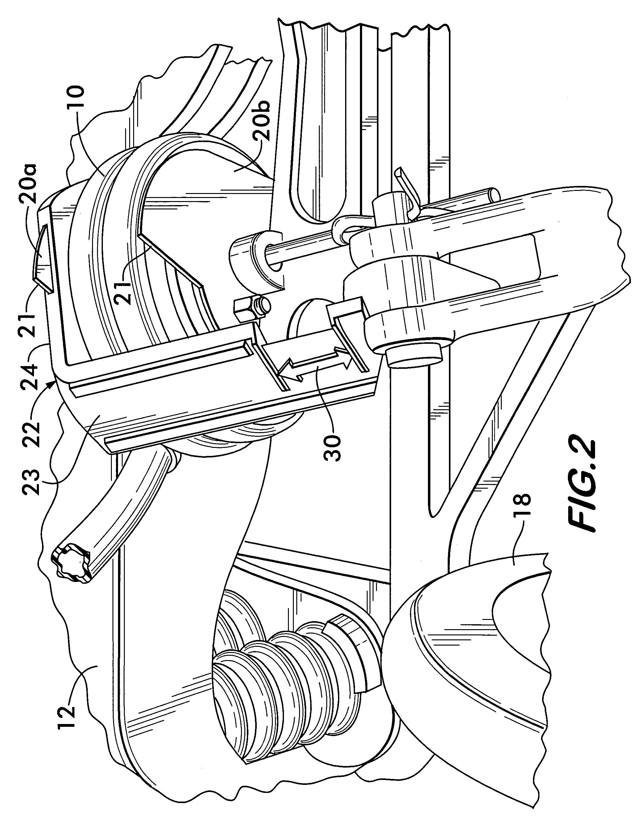
[0009]In FIGS. 1 and 2, an air bag-type actuator 10 of conventional construction is seen mounted on the bolster 12 of a conventional rail car truck. The actuator is connected to a supply of air under pressure via a brake line 14, and upon delivery of pressure thereto, expands axially away from the bolster 12 to move a brake lever 16, thereby moving the brakes (not shown) into engagement with the rail car wheels, a portion of one of which is shown at 18 in FIGS. 1 and 2. In FIGS. 1 and 2, the brake actuator is shown in the retracted position.

[0010]Air bag-type actuators of the type described are conventionally provided with a pair of measuring plates 20a and 20b affixed to the movable and fixed ends of the actuator respectively. The plates 20a and 20b are of substantially identical shape.

[0011]The purpose of the measuring plates 20a and 20b is to provide a rail car inspector with reference points for measuring the amount of travel of the movable end of the actuator when the brakes ar...


PUM


Abstract

An indicator device indicating the travel of an air bag-type brake actuator when brakes are applied includes a stationary indicator plate having a cut out extending alongside the path of travel of the actuator. The cut out includes side edges positioned at acceptable minimum and maximum actuator expansion distances giving an indication of proper functioning of the brakes. The device further includes an integral mounting arm for mounting on a plate in the fixed end of the actuator. The mounting arm includes a slot for receiving an upper edge of the stationary measuring plate and a stud on a resilient portion of the arm. An aperture on the stationary measuring plate receives the stud when the arm is mount on it.

Description

FIELD OF THE INVENTION[0001]This invention relates to brake actuators, especially brake actuators of the air bag or bellows type, for actuating the brakes of rail cars and similar vehicles and more particularly relates to an indicator for indicating the amount of air bag actuator travel when the brakes are applied.BACKGROUND OF THE INVENTION[0002]Conventional air bag or bellows-type actuators for rail car brakes are typically mounted on the rail car truck bolster. The air bag-type actuators are in construction structurally similar to a bellows. They are formed of a flexible fabric material which expands axially under pressure supplied by the rail car reservoir to move the brake shoes into engagement with the wheels of the rail car. In the description which follows, the terms “air bag-type” and “bellows-type” are used interchangeably. The actuator is pressurized in response to release of air under pressure from the rail car reservoir to cause axial expansion of the actuator which, in...

Claims


Application Information

Patent Timeline
Patent Type & Authority Patents(United States)
IPC IPC(8): F16D66/02
CPCF16D66/028
Inventor MURPHY, WAYNE H.
Owner PENNSY CORP
Learn More