
Rail seat assembly

Active Publication Date: 2006-09-05
PROGRESS RAIL SERVICES
View PDF13 Cites 11 Cited by
  • Summary
  • Abstract
  • Description
  • Claims
  • Application Information

AI Technical Summary

Benefits of technology

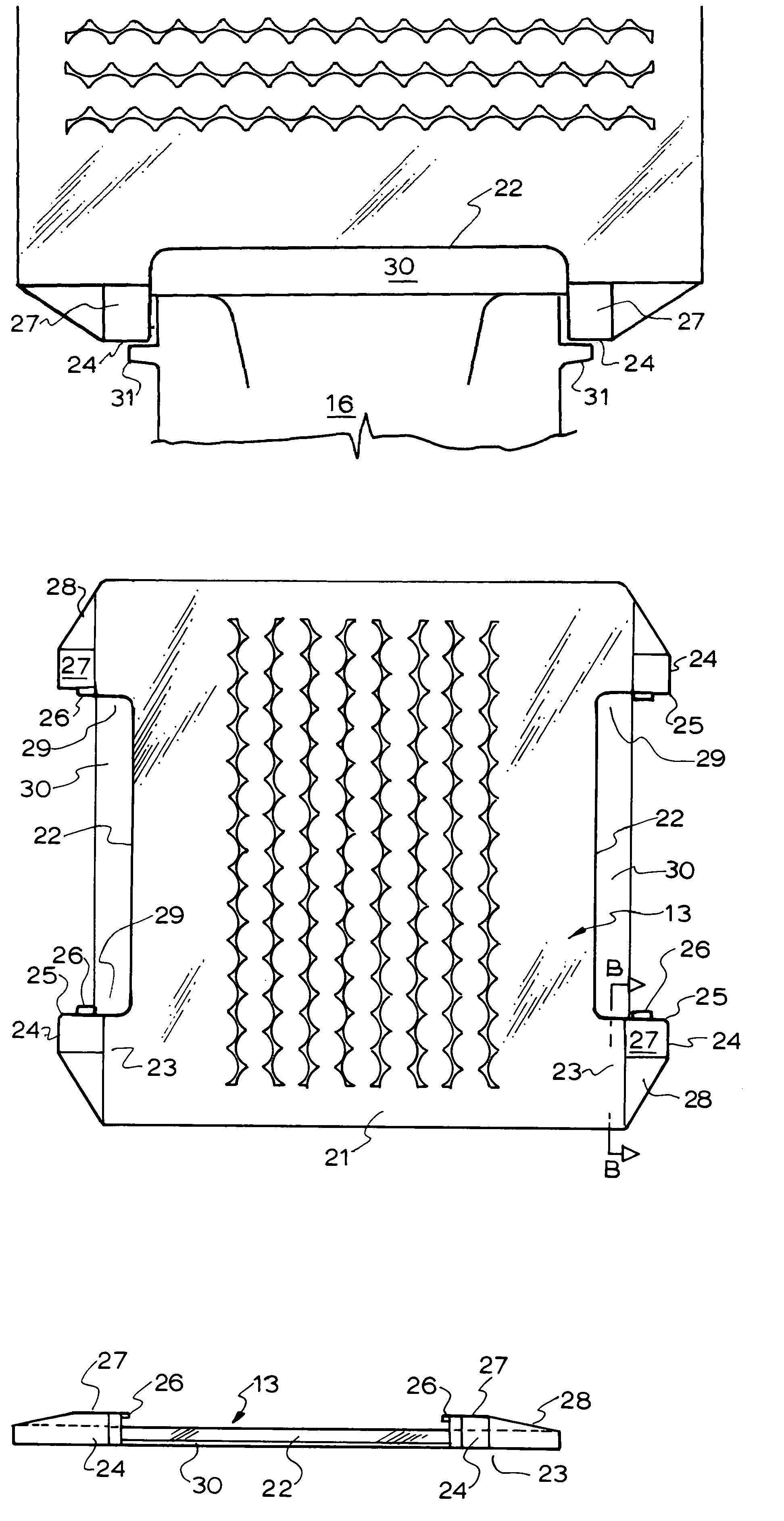
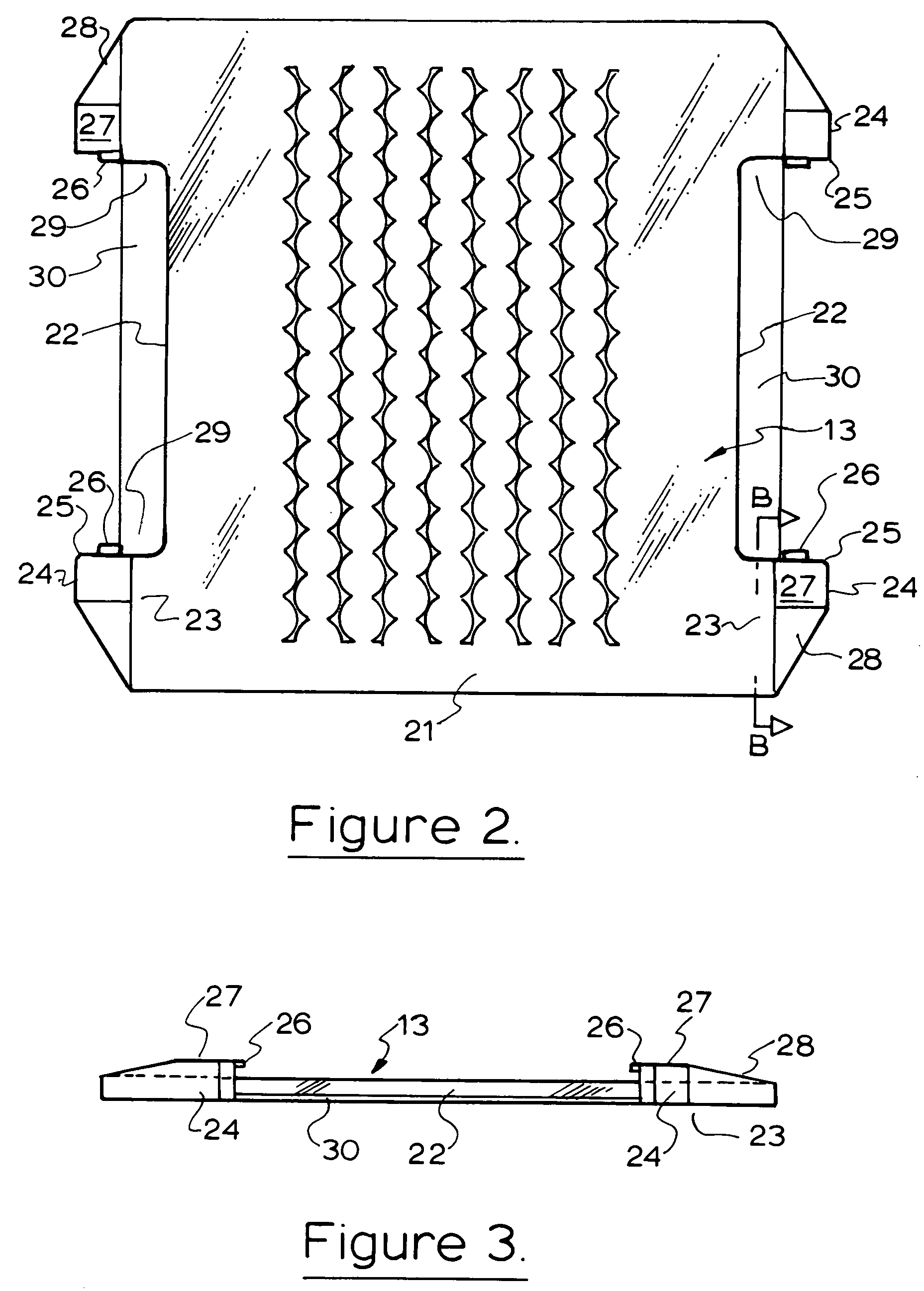
[0017]In order to retard displacement of the pads prior to the rail being placed in position the pad projections have resilient tabs projecting laterally toward the sides of the shoulders so that they are deformed when the pads are placed on the rail seat to create a force fit between the pads and the shoulders to prevent accidental displacement of the pads during transit and installation.

Problems solved by technology

Because this portion of the pad is thin and flexible or non existent it can not provide a positive register for the pad against the support shoulder.

Method used


Image

  • Rail seat assembly
  • Rail seat assembly
  • Rail seat assembly

Examples


Embodiment Construction

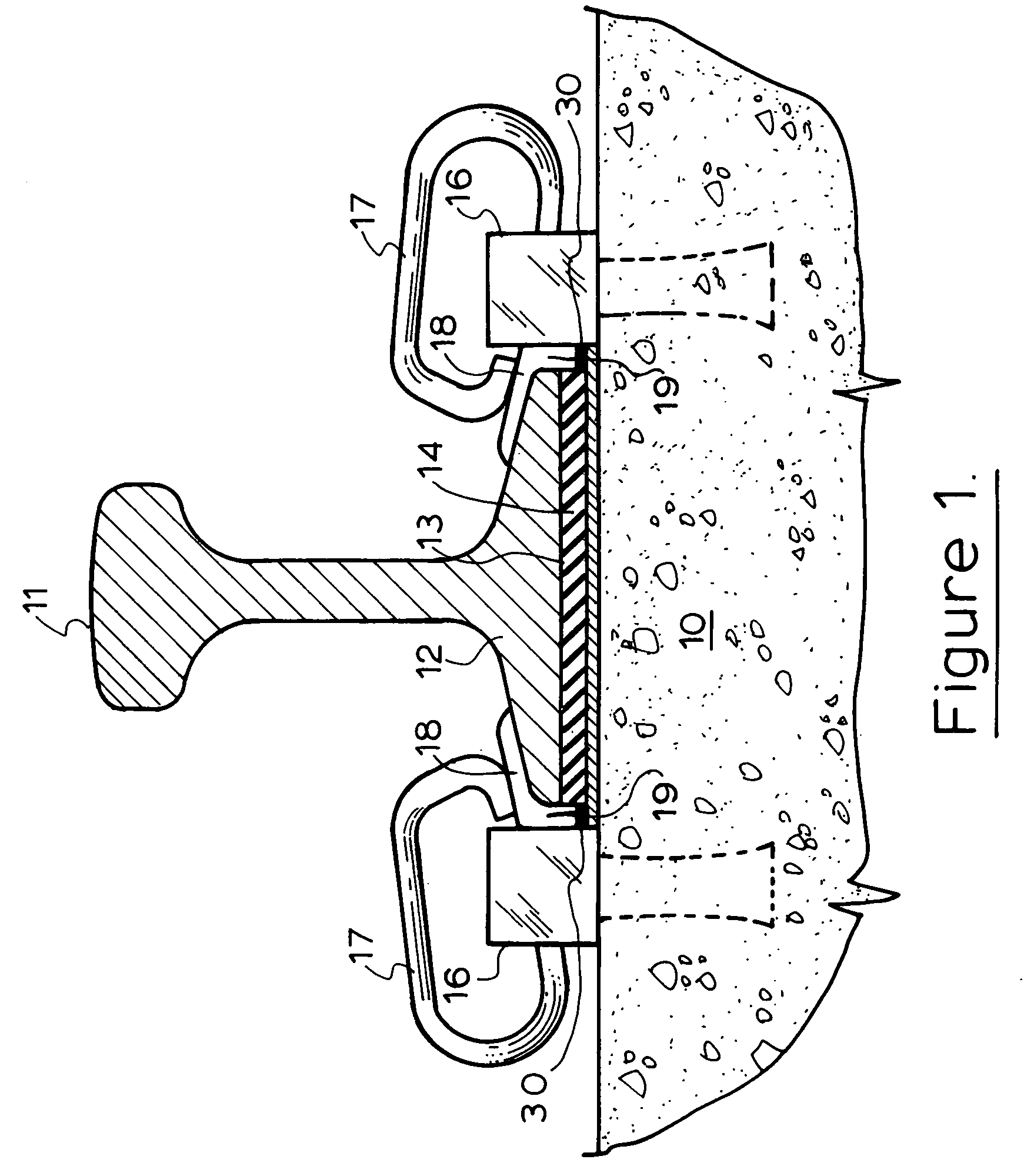
[0025]The rail seat of this invention is based on concrete rail seats as described in U.S. Pat. Nos. 4,618,093 and 6,045,052 except that a deep post insulator is used which has a vertical portion which fits between the rail base and the rail clamp support shoulder and extends downwardly below the level of the bottom edge of the rail. The rail seat consists of a rail tie 10 having cast in place clamp shoulders 16 to which rail clamps 17 are fitted. These clamps 17 hold the rail 11 in place. The rail base 12 lies on a rail pad 13 which in turn lies on a rail plate 14. A deep post insulator 18 lies between the rail base 12 and the toe of the rail clamp 17 and the rail face of the support shoulder 16. In this embodiment a deep post insulator 18 is used and the post 19 extends below the bottom edge of the rail base 12 into a recess provided in the rail pad 13.

[0026]The rail pad 13 is made from a hard elastomeric material such as natural or synthetic rubber or polyurethane. The central po...


PUM


Abstract

A rail seat which includesa) a rail tieb) a pair of rail fastening support shoulders mounted on said rail tie so that a rail can be held to the tie between said shoulders each shoulder having a a rail face and side portions on each side of said rail face extending away from the railc) a rail pad adapted to lie on said tie between said shoulders which has a pair of projections extending parallel to the tie along side each side portion of each shoulder.The rail seat is adapted to be used with a deep post insulator and incorporates a rib on the support shoulder extending from each side portion against which a face of the rail pad projections abut to locate the pad in position to accommodate the post of the insulator. The rail pad projections are proportioned to prevent the pad from moving out of position under the creep load conditions present when rail cars pass over the rail seat. A resilient tab is provided on each projection to abut the side portions of the support shoulder to retain the pad in position between the support shoulders during transport of the rail tie to the installation site.

Description

FIELD OF THE INVENTION[0001]This invention relates to rail roads and in particular preassembled rail fastening components for rail ties.BACKGROUND TO THE INVENTION[0002]Rail pads are used to electrically and dynamically insulate the rail tie from the rail and U.S. Pat. Nos. 4,618,093 and 5,203,502 are examples of rail pads used with elastic rail clip support shoulders that are fixed to the tie on either side of the rail.[0003]Often shims and gaskets are also placed under the rail pad.[0004]It is now common practice for the rail pads to be placed in the rail seats at the rail tie manufacturing plant in order to save time at the track installation. The ties are usually stacked on flat rail cars at the tie plant. There may be 4 layers of ties with wooden dunnage between each layer. The dunnage sits on the rail seats. The pads gaskets and shims on the top layer may be blown off in transit or from any tie during installation. If this is not noticed and the rail ties are fed onto the trac...

Claims


Application Information

Patent Timeline
IPC IPC(8): E01B19/00E01B9/68
CPCE01B9/68
Inventor YOUNG, HARTLEY FRANK
Owner PROGRESS RAIL SERVICES
Learn More