
Air bearing slider for disk drive

a technology of air bearings and disk drives, which is applied in the direction of maintaining the head carrier alignment, recording information storage, instruments, etc., can solve the problems of deteriorating disk drive performance, generating friction, and reducing the life of the head, so as to achieve rapid lifting

Inactive Publication Date: 2006-08-29
SAMSUNG ELECTRONICS CO LTD
View PDF12 Cites 21 Cited by
  • Summary
  • Abstract
  • Description
  • Claims
  • Application Information

AI Technical Summary

Benefits of technology

[0020]To solve the above and / or other problems, the present invention provides an air bearing slider of a disk drive which can be lifted quickly at a low rotation speed of a disk and minimize a change in the flying height according to a change in the rotation speed of the disk after being lifted.
[0035]Accordingly, the air bearing slider according to the present invention can be rapidly lifted at a low rotation speed of the disk. After the slider is lifted, the change in the flying height of the slider according to a change in the rotation speed of the disk is minimized.

Problems solved by technology

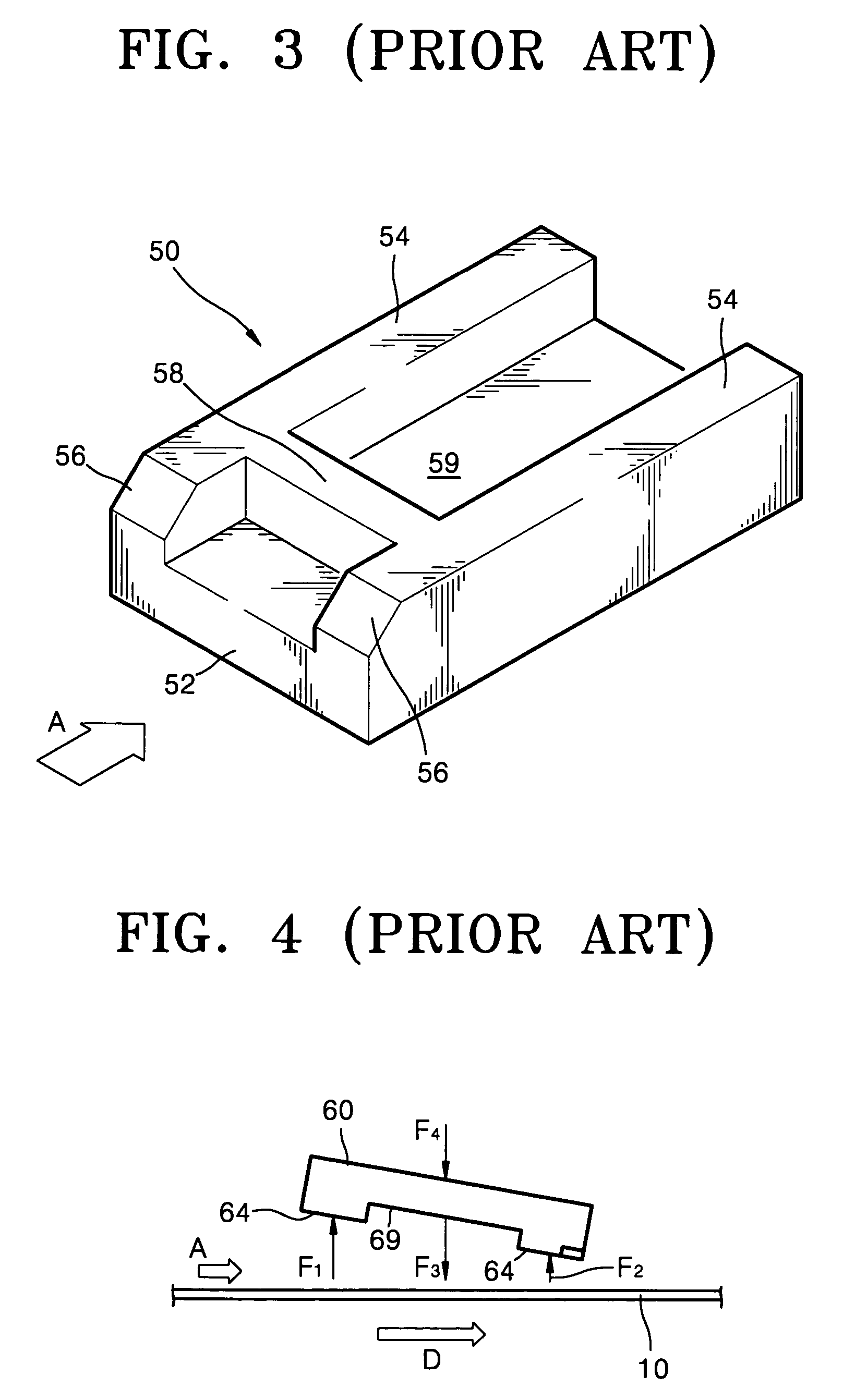
However, since the conventional air bearing slider is not lifted to a sufficient height until the rotation speed of the disk reaches a regular rpm, a surface of the slider facing the disk, that is, the air bearing surface, contacts the surface or bumper of the disk so that friction may be generated.
In this case, the head may be damaged, or debris may be generated which contaminates the disk or head, by which the life span of the head is reduced and performance of the disk drive is deteriorated.
Even if the slider and disk are abraded for a very short time, frequent generation of such friction makes the problems serious.

Method used


Image

  • Air bearing slider for disk drive
  • Air bearing slider for disk drive
  • Air bearing slider for disk drive

Examples


Embodiment Construction

[0046]Reference will now be made in detail to the embodiments of the present invention, examples of which are illustrated in the accompanying drawings, wherein like reference numerals refer to the like elements throughout. The embodiments are described below to explain the present invention by referring to the figures.

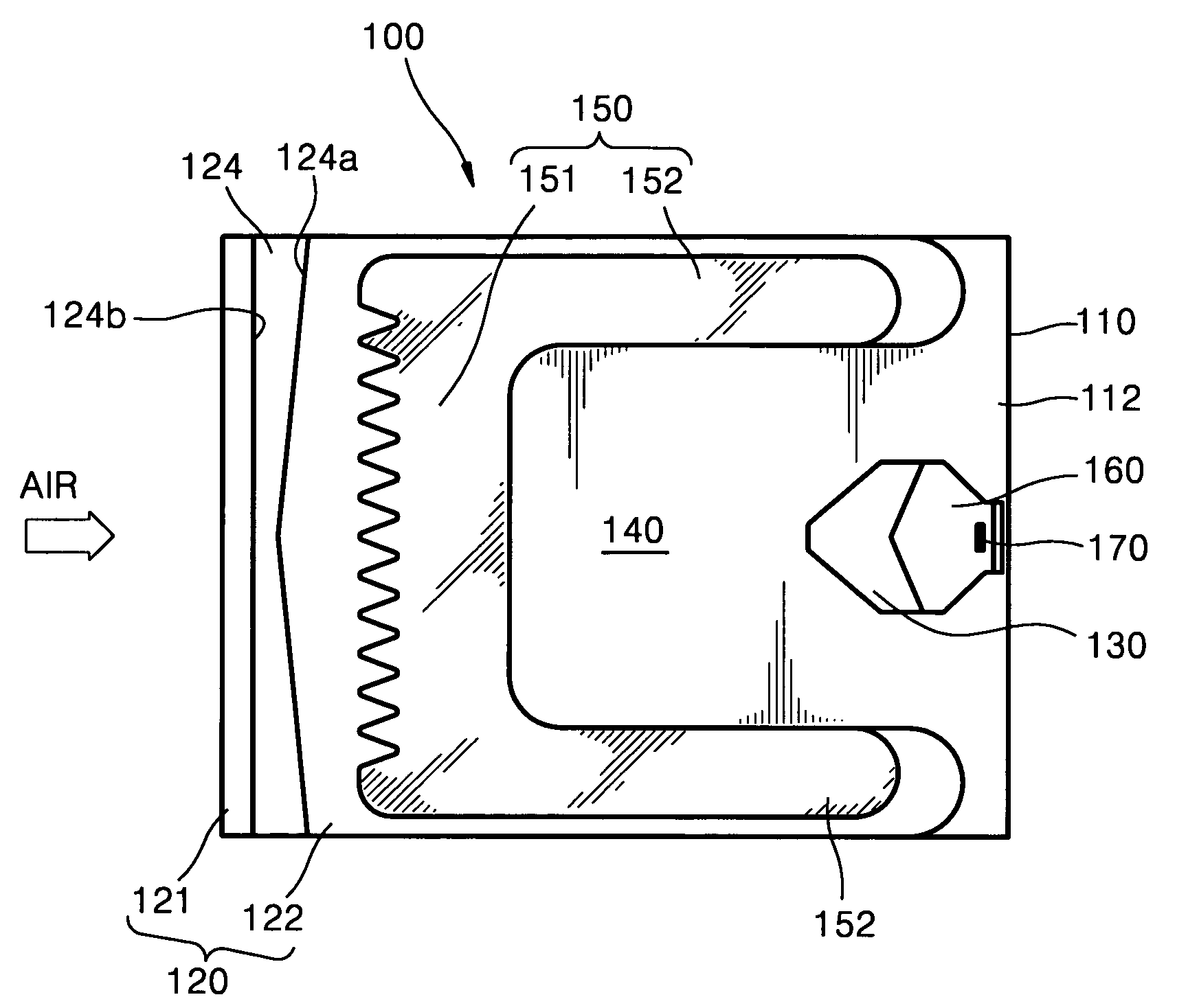
[0047]Referring to FIGS. 6A and 6B, an air bearing slider 100 according to an embodiment of the present invention includes a body 110 having a thin block shape. First and second rail bases 120 and 130 and a negative pressure cavity 140 are arranged on a surface 112 of the body 110 facing a disk (not shown).

[0048]The first rail base 120 protrudes a predetermined height, for example, 1–1.5 μm, from the surface 112 of the body 110 facing the disk, and has a U shape having one side open to a trailing end portion of the body 110.

[0049]A first positive pressure generating rail portion 150 is provided on an upper surface of the first rail base 120. The first positive pressure...


PUM


Abstract

An air bearing slider of a disk including a body having a surface facing a disk; a first rail base protruding from the surface facing the disk; a first rail portion protruding from the first rail base, the first rail portion including a cross rail separated from a leading end portion of the first rail base and extending perpendicular to a direction in which air enters, and a pair of side rails respectively extending from both ends of the cross rail parallel to the direction in which air enters; a negative pressure cavity defined by the first rail base; a second rail base protruding from the surface facing the disk; a second rail portion protruding from the second rail base; and an air flow channel disposed between the leading end portion of the first rail base and the cross rail, extending perpendicular to the direction in which air enters.

Description

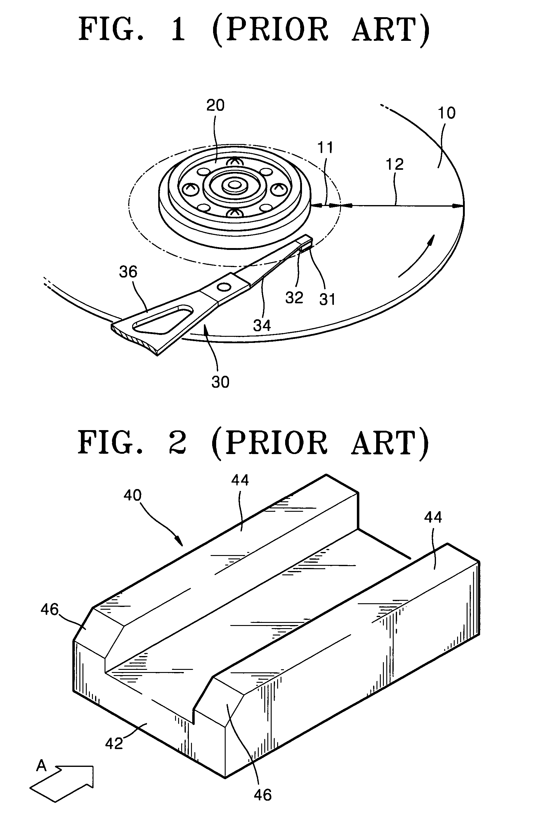
CROSS-REFERENCE TO RELATED APPLICATIONS[0001]This application claims the priority of Korean Patent Application No. 2003-8003, filed on Feb. 8, 2003 in the Korean Intellectual Property Office, the disclosure of which is incorporated herein in its entirety by reference.BACKGROUND OF THE INVENTION[0002]1. Field of the Invention[0003]The present invention relates to an air bearing slider of a disk drive, and, more particularly, to an air bearing slider which can improve a take-off characteristic.[0004]2. Description of the Related Art[0005]A disk drive, for example, a hard disk drive (HDD), is an auxiliary memory device of a computer which records data on a disk or reproduces data stored on the disk by using a read / write head.[0006]FIG. 1 is a perspective view illustrating part of a typical hard disk drive. Referring to FIG. 1, a typical hard disk drive includes a magnetic disk (hard disk) 10 which is a recording medium for data recording, a spindle motor 20 rotating the disk 10, a read...

Claims


Application Information

Patent Timeline
IPC IPC(8): G11B5/60G11B21/21
CPCG11B5/6005G11B5/6082G11B21/21
Inventor KANG, TAE-SIK
Owner SAMSUNG ELECTRONICS CO LTD
Learn More