
Methods and systems for controlling a height of munition detonation

a technology of munition and height, applied in the direction of reradiation, lighting and heating equipment, instruments, etc., can solve the problems of increasing the risk of air defense, exposing the aircraft and crew, and consuming a lot of time,

Inactive Publication Date: 2006-08-29
HONEYWELL INT INC
View PDF17 Cites 30 Cited by
  • Summary
  • Abstract
  • Description
  • Claims
  • Application Information

AI Technical Summary

Benefits of technology

The system enables munitions to detonate at precise altitudes, enhancing mission effectiveness by ensuring targeted damage and reducing exposure to air defenses, while being cost-effective and applicable to smaller munitions.

Problems solved by technology

However, dropping conventional munitions from a low altitude exposes the aircraft and crew to air defenses, for example, anti-aircraft artillery and surface-to-air missiles since.
Alternatively, to deliver munitions in high numbers, it is frequently necessary fly an undesirably large number of missions which is expensive, time consuming, and exposes more aircraft and crew to air defenses.
However these systems are typically related to guiding the munition to a desired location, and are not typically related to detonation of the munition.
Furthermore, such guidance systems are expensive and cannot affordably be incorporated into smaller munitions.
Rather, such a detonation is likely to result in severe damage to a smaller area.

Method used


Image

  • Methods and systems for controlling a height of munition detonation
  • Methods and systems for controlling a height of munition detonation
  • Methods and systems for controlling a height of munition detonation

Examples


Embodiment Construction

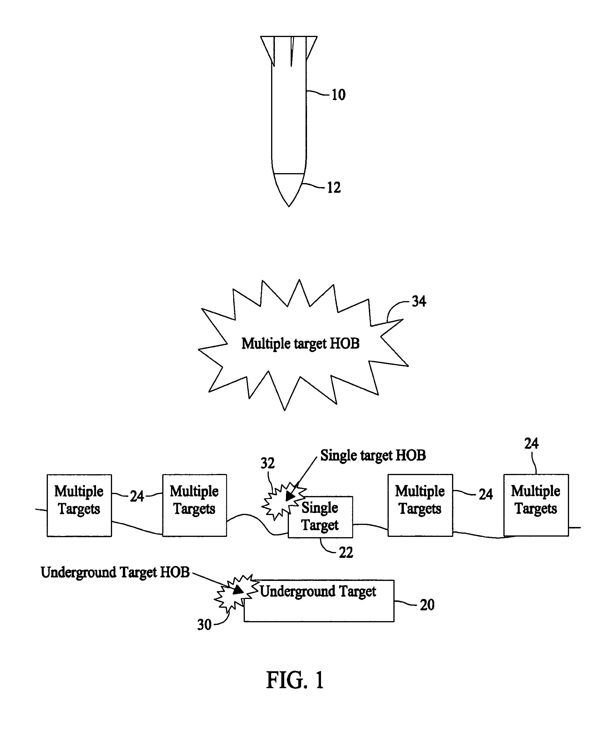
[0012]FIG. 1 is a diagram illustrating a munition 10, for example, a bomb or missile, which includes an altitude sensor 12. Altitude sensor 12 is utilized in controlling a height of burst, or detonation altitude, of munition 10. Equipped with altitude sensor 12, munition 10 is configured for use in multiple missions. As illustrated in FIG. 1, munition 10 is configurable for use against an underground target 20, a single ground level target 22, and multiple ground level targets 24.

[0013]In one embodiment, munition 10 is configured with a detonation altitude (e.g., a height of burst (HOB)) prior to launch from an aircraft (not shown). The programmed detonation altitude enables detonation at the desired height above (or below) ground level dependent on the particular mission. If munition 10 is to be utilized against underground target 20, it is configured with an underground target detonation altitude (HOB) 30, such that munition 10 will not detonate until a predetermined time has pass...


PUM


Abstract

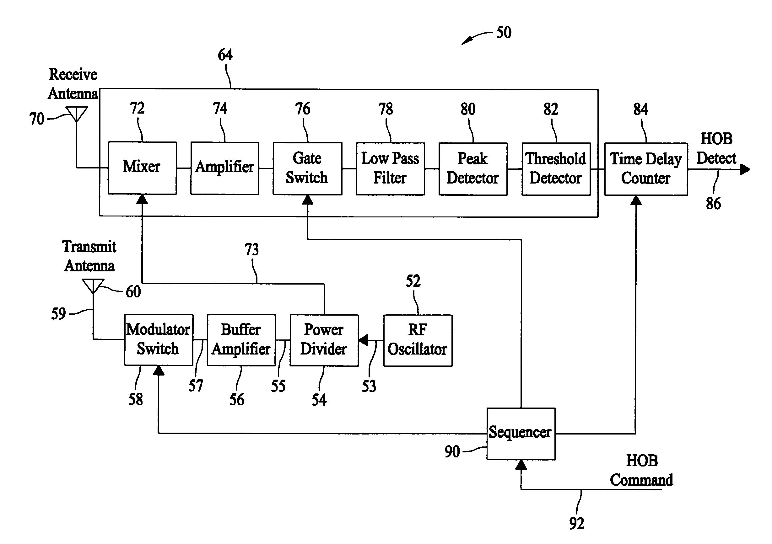
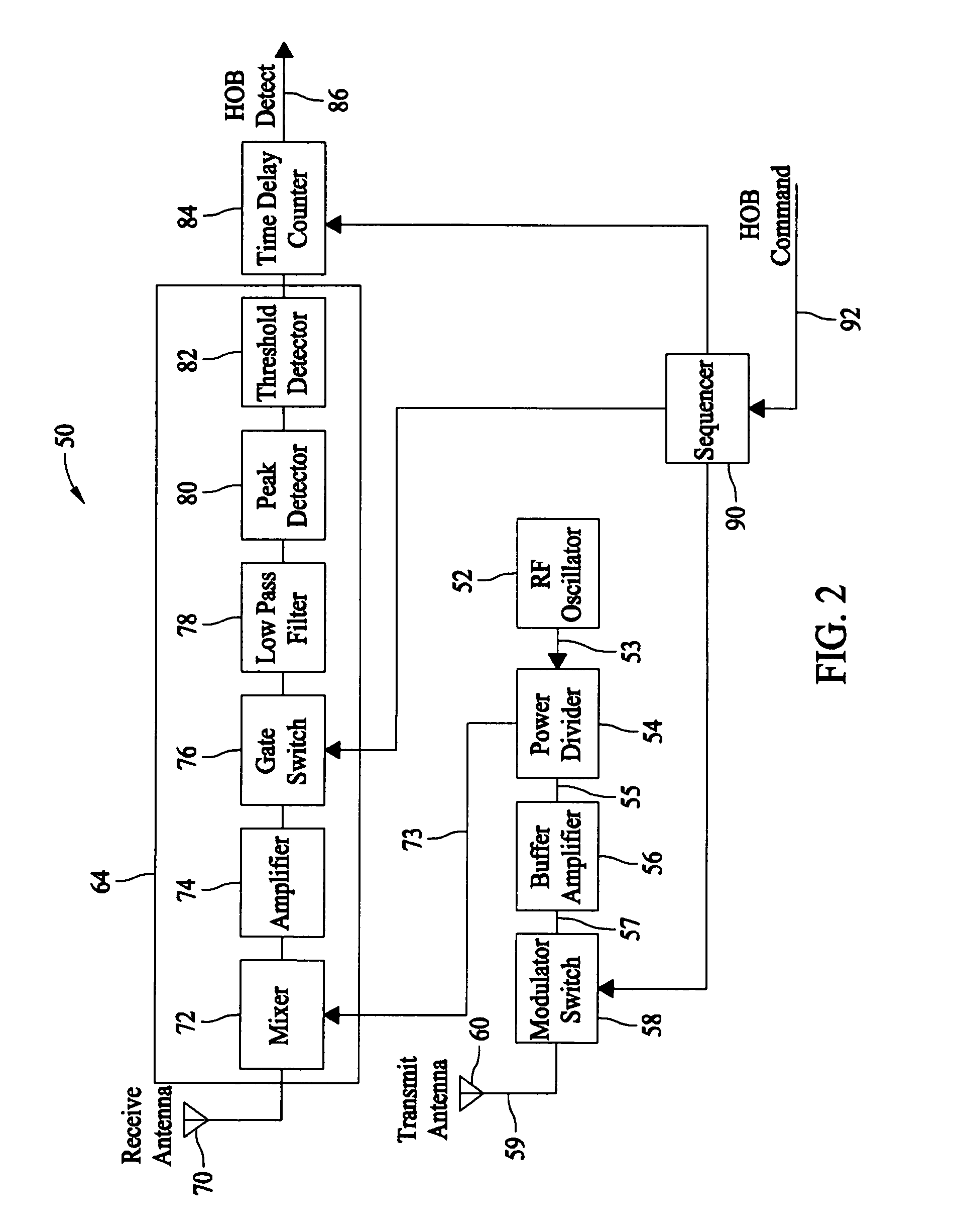
A unit is described that is configured to control detonation of a munition such that the munition is detonated at a desired altitude. The unit includes a radar transmitter, a radar receiver that includes a radar range gate, and a sequencer. The sequencer is configured to receive a detonation altitude and set the range gate based on the received detonation altitude. The unit is also configured to output a detonation signal when radar return pulses received by the receiver aligned with gate delay pulses from the range gate.

Description

BACKGROUND OF THE INVENTION[0001]This invention relates generally to controlling detonation of weapons, and more specifically, to methods and systems for controlling a height, or altitude, of munition detonation.[0002]Conventional munitions dropped or launched from aircraft is either released with a high accuracy, or in large numbers, in order to effectively destroy a desired target. To achieve a high accuracy, it is frequently necessary to drop such munitions from an undesirably low altitude. However, dropping conventional munitions from a low altitude exposes the aircraft and crew to air defenses, for example, anti-aircraft artillery and surface-to-air missiles since. Alternatively, to deliver munitions in high numbers, it is frequently necessary fly an undesirably large number of missions which is expensive, time consuming, and exposes more aircraft and crew to air defenses.[0003]To overcome these problems, smart munitions have been developed. Some smart munitions utilize a guida...

Claims


Application Information

Patent Timeline
Patent Type & Authority Patents(United States)
IPC IPC(8): F42C13/04G01S13/16G01S13/18
CPCF42C13/04F42C13/047G01S13/882G01S7/038
Inventor HAGER, JAMES R.BACKES, GLENREILLY, TIMOTHY J.
Owner HONEYWELL INT INC
Learn More