Amplifier circuit

a technology of amplifier circuit and circuit, applied in the field of amplifier circuit, can solve the problems of increasing current consumption and complicated circuit architecture of the output stage of the operational amplifier, and achieve the effect of reducing power consumption and simple circuit architectur

Inactive Publication Date: 2006-08-29
FUJI ELECTRIC SYST CO LTD
View PDF7 Cites 2 Cited by
  • Summary
  • Abstract
  • Description
  • Claims
  • Application Information

AI Technical Summary

Benefits of technology

[0010]With such an amplifier circuit, it is possible to provide an amplifier circuit having a simple circuit architecture and that includes a push-pull output as an operational principle. Further, by adopting the push-pull output architecture, it is possible to suppress a bias current of the push-pull output stage at the time of still operation with no signals and to allow the flow of a large current at the time of a heavy load whereby the power consumption can be reduced.

Problems solved by technology

However, when the push-pull output is adopted, to provide a stable operational amplifier in which an output voltage does not receive the influence of the fluctuation of output voltage and the fluctuation of temperature or the like, there has been a drawback that the bias control method of gates of the PMOS transistor and the NMOS transistor (bases in bipolar transistors) used in an output stage is difficult and hence, the circuit architecture of the output stage of the operational amplifier becomes complicated whereby current consumption is increased.

Method used


Image

  • Amplifier circuit
  • Amplifier circuit
  • Amplifier circuit

Examples


Embodiment Construction

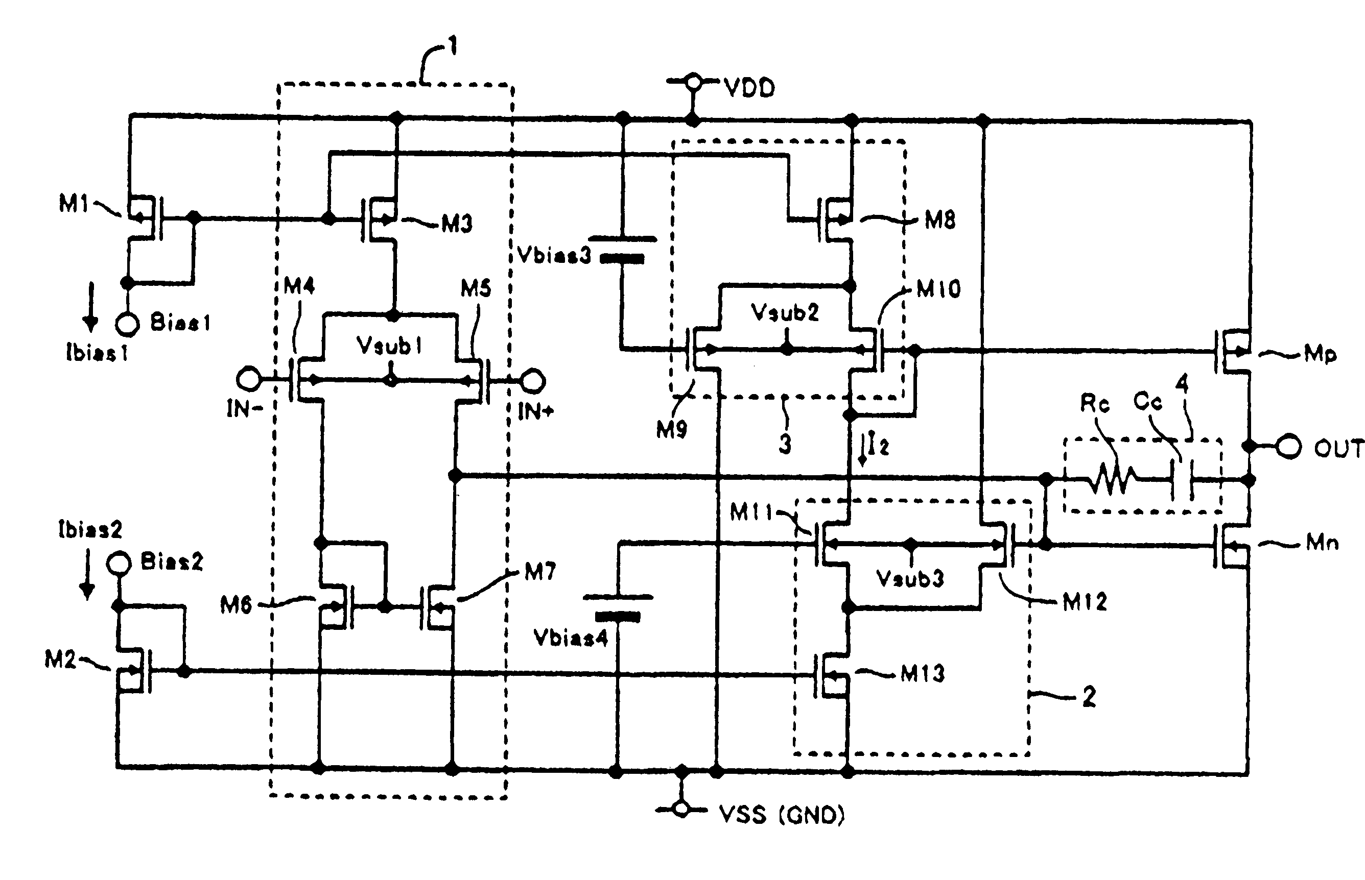
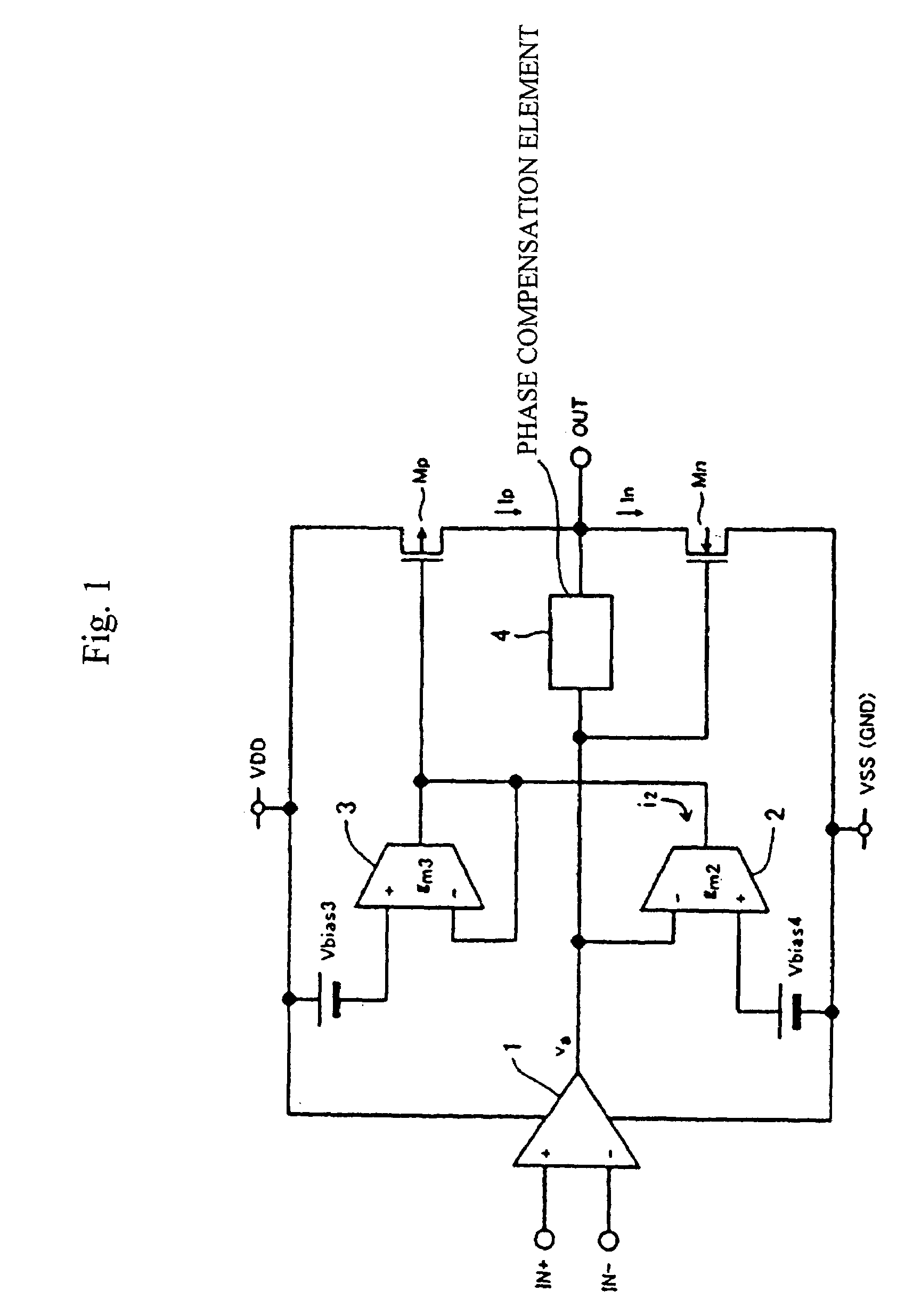
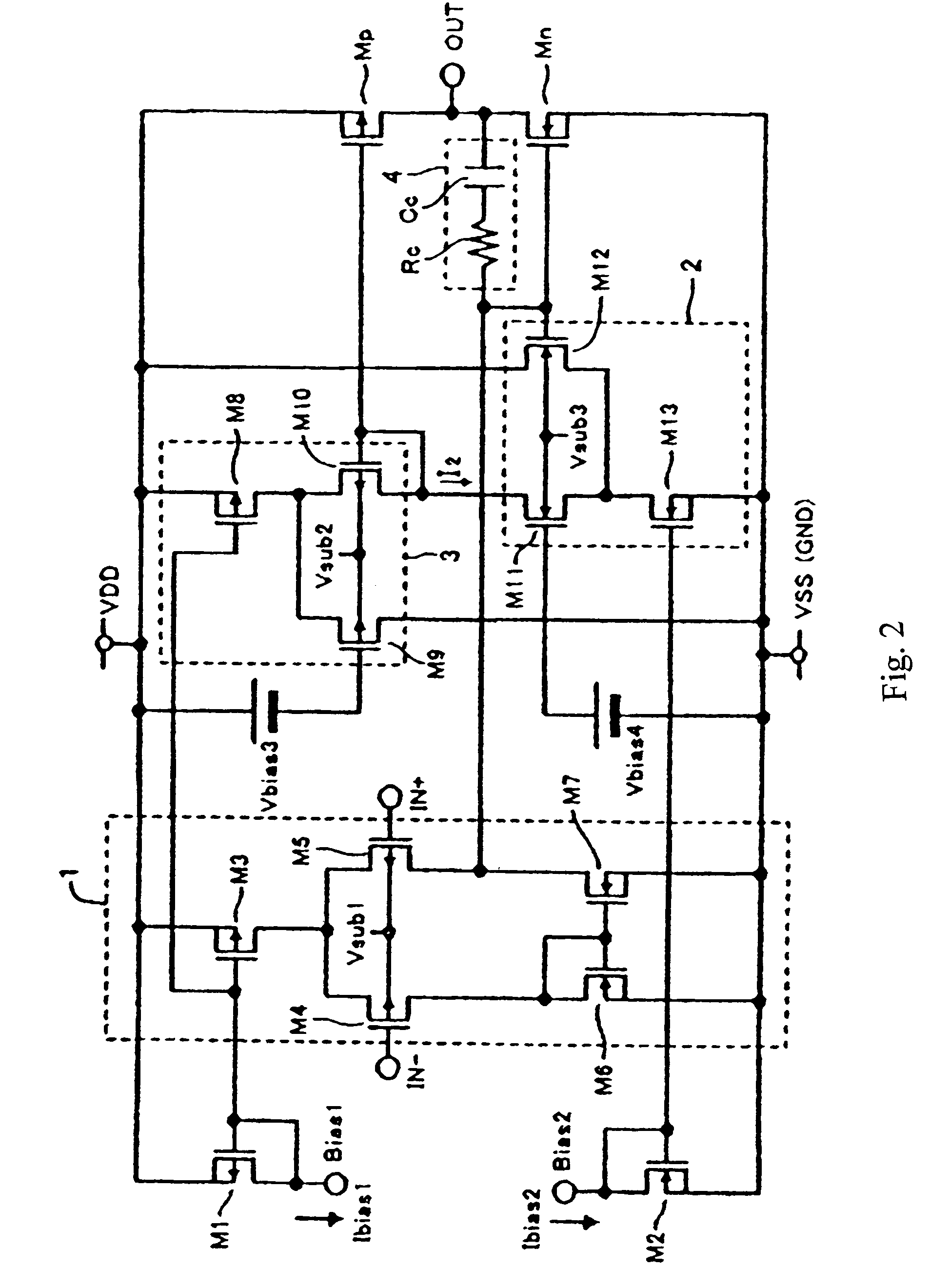
[0019]FIG. 1 is a circuit diagram showing the basic architecture of an amplifier circuit according to the present invention. The amplifier circuit includes a differential amplifier 1 in a first amplifying stage, a first transconductance amplifier 2 and a second transconductance amplifier 3 in a second amplifying stage, and a first output transistor Mp and a second output transistor Mn which form the push-pull outputs having polarities opposite from each other and use the push-pull outputs as an output OUT of this amplifier circuit in an output stage. Further, a phase compensation element 4 is provided between the output of the differential amplifier 1 and the output OUT of the amplifying circuit.

[0020]The differential amplifier 1 includes an inverted input IN−, a non-inverted input IN+ and an output and a difference signal between signals inputted to the inverted input IN− and the non-inverted input IN+ is amplified and then is outputted from the output.

[0021]The first transconducta...


PUM


Abstract

An amplifier circuit has a simple circuit architecture that enables a push-pull output function while exhibiting low power consumption. The amplifier circuit includes a first transconductance amplifier to which an output of a two-input differential amplifier and a first bias voltage are input. An output of the first transconductance amplifier is connected to another input and an output of a second transconductance amplifier, which has one input thereof connected to an output of the first transconductance amplifier and a gate of a first output transistor. The output of the differential amplifier is connected to a gate of a second output transistor, which has the polarity opposite to the polarity of the first output transistor. Drains of the first and the second output transistors are connected to each other thus constituting a push-pull output.

Description

BACKGROUND OF THE INVENTION[0001]The present invention relates to an amplifier circuit, and more particularly, to an amplifier circuit capable of performing a push-pull output and having a reduced power consumption, which is applied to a semiconductor integrated circuit for amplifying signals and performing impedance conversion.[0002]An example of a conventional amplifier circuit capable of performing a push-pull output is shown in FIG. 6 and described in Japanese Patent Publication 2688477. In this amplifier, a PMOS transistor (QPf) and an NMOS transistor (Qnf) which adopt a complementary architecture are connected in a push-pull type configuration as final components of a class AB output stage or a class B output stage, wherein nodes thereof constitute output terminals (OUT) of the stage. Two transconductance amplifier circuits (Tp, Tn) have respective output terminals thereof connected to gate terminals of the PMOS transistor (Qpf) and the NMOS transistor (Qnf), have respective i...

Claims


Application Information

Patent Timeline
Patent Type & Authority Patents(United States)
IPC IPC(8): H03F3/45H03F1/02H03F3/30H03J3/30
CPCH03F3/3022H03F3/45475H03F3/45179H03F2203/30144H03F3/45
Inventor MIZOE, KIMIYOSHI
Owner FUJI ELECTRIC SYST CO LTD
Why Eureka
Try Eureka