Connecting flange for tubular components and wind turbine tower employing same

a technology of connecting flanges and tubular components, which is applied in the direction of motors, structural elements, building components, etc., can solve the problems of multiple change of direction and flow of forces in the flange connection, and achieve the effect of facilitating load, facilitating expansion, and optimizing the flow of forces

Inactive Publication Date: 2006-08-29
WOBBEN ALOYS
View PDF27 Cites 20 Cited by
  • Summary
  • Abstract
  • Description
  • Claims
  • Application Information

AI Technical Summary

Benefits of technology

[0006]An object of one aspect of the invention, in contrast, is to provide an annular flange that is less prone to damage resulting from the stresses associated with its intended use.
[0008]In one aspect of the present invention, in contrast, an annular flange has a tubular portion for attaching the flange to one end of a tubular component. A flange collar radially adjoins one end of said portion, preferably inwards, and the flange has a preferably planar flange surface facing axially away from said portion. The outer wall of the tubular portion is conical and can therefore be attached to a conically tubular component to produce a contiguous outer contour. This significantly improves the flow of forces from the conically tubular component into the flange collar, because a deflection of the flow of forces—which generally causes a concentration of stresses and possibly over—stressing of components—is thus prevented.
[0009]The flange collar adjoins the tubular portion, preferably radially inwards, so that, when using the flange according to one aspect of the invention to connect tower segments of a wind turbine, for example, the flange collar—as well as other connection elements such as flange connecting screws, which produce connecting force and positive locking by means of through bores arranged axially on the circumference—are positioned inside the tower, and thus protected against weathering.
[0012]In order to optimize further the flow of forces through the preferably planar flange surface and through a connecting screw in the preferred through bore, said through bore is preferably surrounded by a recess in the flange surface. Owing to greater length of expansion, this has a favorable effect on the load imposed on the connecting screw in the through bore, and favorably displaces the zone of contact of one flange surface with a complementary flange surface around the through bore into the radially outer and inner edges of the flange surface.

Problems solved by technology

Attaching notorious annular flange elements, with straight cylindrical attachment portions aligned in the direction of the cylinder axis, to conically tubular tower components, in the manner intended by the prior art, results in a flow of forces in the flange connection that may even exhibit multiple changes of direction, and is also aesthetically disadvantageous.

Method used


Image

  • Connecting flange for tubular components and wind turbine tower employing same
  • Connecting flange for tubular components and wind turbine tower employing same

Examples


Embodiment Construction

[0014]Aspects of invention will now be described with reference to the enclosed drawing.

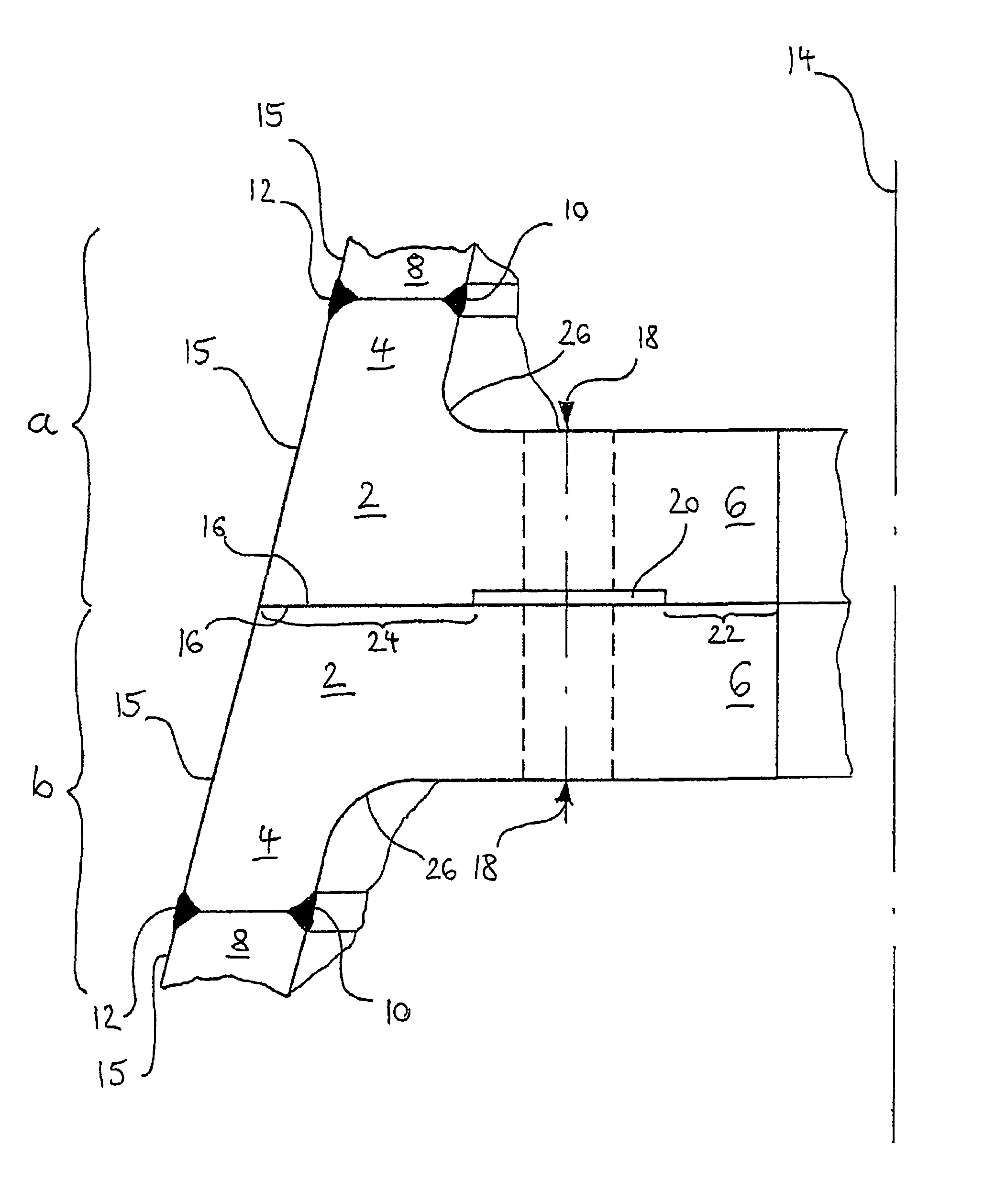
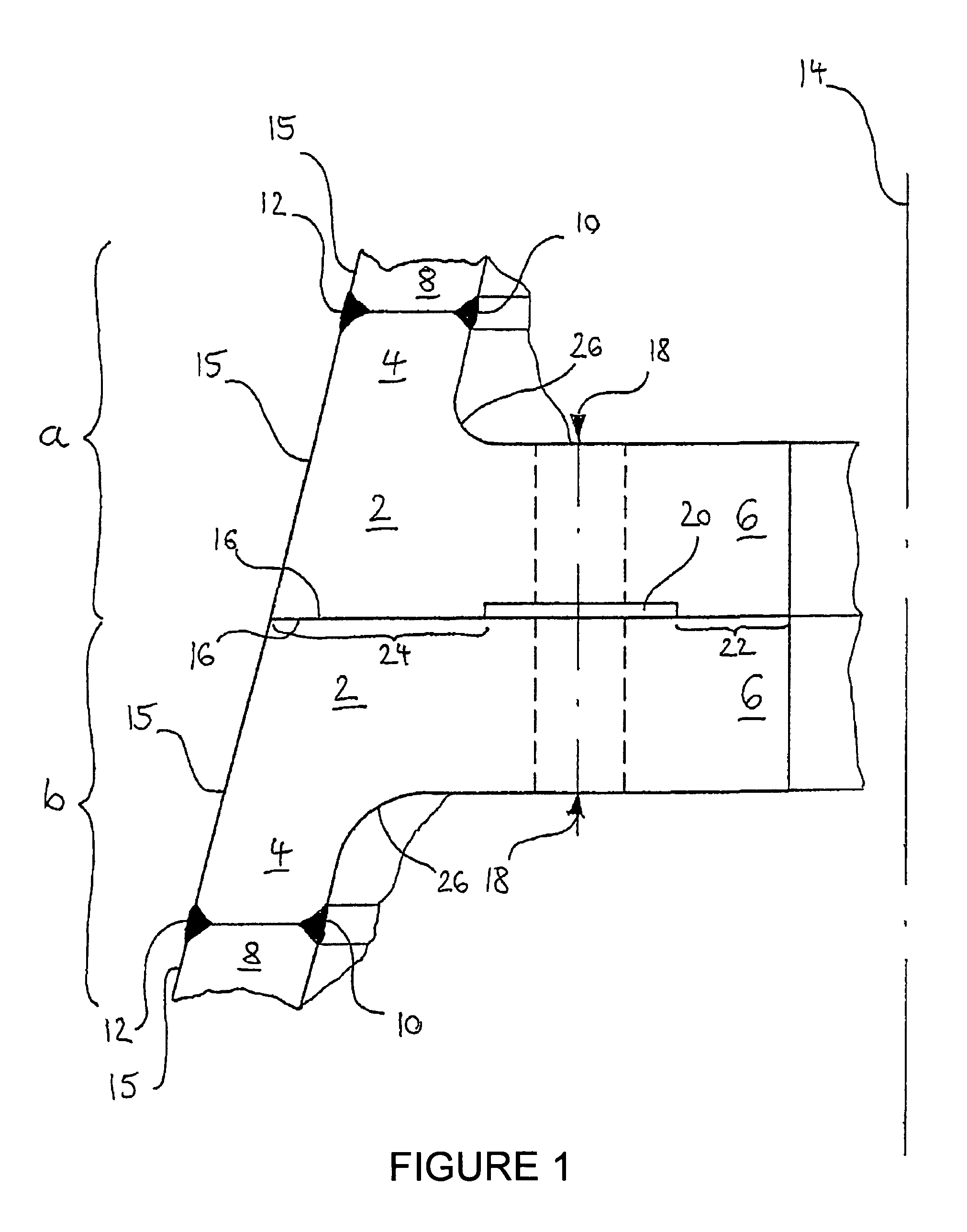
[0015]FIG. 1 shows a cross-section through a flange connection according to one embodiment of aspects of the invention, comprising two flanges that are each attached to a conically tubular component.

[0016]The flange connection shown in FIG. 1 is formed by two flanges 2 (whereby, when differentiation is necessary, the upper components and elements, in other words those associated with the upper of the two flanges 2 shown in the drawing, are referred to as ‘a’ and the lower ones as ‘b’). Both flanges 2 have a tubular portion 4 and a flange collar 6 that adjoins one end of the tubular portion 4 radially inwards. A tubular component 8 adjoins the other end of each tubular portion 4 and is welded to the annular flange connection 2 by means of a radially inner and a radially outer weld seam 10, 12. Flanges 2 are made of welding steel.

[0017]The arrangement in FIG. 1 thus described is configured overall ...


PUM


Abstract

The present invention relates to an annular flange connection for attachment to one end of a tubular component. An object of one aspect of the invention is to provide an annular flange that is less prone to damage resulting from the stresses associated with the intended use. In one embodiment, an annular flange connection with a tubular portion for attachment to one end of a tubular component, in particular to a tower segment for assembling a wind turbine tower, and with a flange collar radially adjoining one end of said tubular portion, with a flange surface facing axially away from said tubular portion, the outer wall of the tubular portion being conical, in particular for attachment to an equally conical component.

Description

RELATED INFORMATION[0001]The present invention relates to an annular flange connection for attachment to one end of a tubular component.[0002]Annular flange connections for connecting tubular components are known, for example from Dieter Lehmann, “Berechnung von L-Flaschen mit unterschiedlichen Kontaktflächen / Ringflanschformen nach DIN 4133”, Ernst & Sohn, Stahlbau 69 (2000) Issue no. 9, pp. 682–687, and such annular flange connections are also widespread in use. In the field of pipeline construction, for example, flange collars are known which radially adjoin the tubular component, said flange collars usually projecting radially outwards at the ends of the pipe section. These flange collars usually have a planar-flange surface facing axially away from the actual pipe member, and have through bores distributed around their circumference. By this means, the tubular components can be aligned with each other, for example as segments of a pipeline, and bolted together with the help of s...

Claims


Application Information

Patent Timeline
Patent Type & Authority Patents(United States)
IPC IPC(8): E04C3/30E04H12/08E04H12/34F03D1/00F03D11/04
CPCE04H12/085E04H12/34F03D1/001Y02E10/728F05B2230/60F03D13/10Y02E10/72Y02P70/50
Inventor WOBBEN, ALOYS
Owner WOBBEN ALOYS
Why Eureka
Try Eureka