Flushing device for a lavatory

Inactive Publication Date: 2006-08-29
GEBRERIT INT
View PDF10 Cites 38 Cited by
  • Summary
  • Abstract
  • Description
  • Claims
  • Application Information

AI Technical Summary

Benefits of technology

[0007]The object of the invention is to provide a flushing device of the abovementioned type which generates less noise and can be adapted to different toilet bowls. The flushing device according to the invention is characterized by at least one pressure-cylinder unit in which flushing water can be subjected to pressure and can be discharged by way of a spring-loaded pressure piston for flushing purposes. In the cases of the flushing device according to the invention, rather than air being compressed, a spring is subjected to stressing. This has the significant advantage that the flushing capacity can be easily optimized, and adapted to specific toilet bowls, by a corresponding setting of the spring or by additional weights.
[0010]According to a development of the invention, it is provided that the pressure-cylinder unit accommodates essentially all the flushing water. A pressure-cylinder unit may be integrated in a very space-saving manner in a cistern body. It is preferably provided that the pressure-cylinder unit is formed, at least in certain regions, by an outer wall of the flushing-cistern body. This allows particularly space-saving and cost-effective production.
[0011]According to a development of the invention, it is provided that the discharge valve is a servovalve. According to a development of the invention, such a valve may have a diaphragm, which closes the valve under water pressure. This allows flushing to take place essentially without any closing noise.

Problems solved by technology

The disadvantage with this flushing device is that it has to be designed for a comparatively high pressure, and that it is difficult to set the appropriate pressure in the vessel.
A flushing device with two outlets and a nozzle in the siphon involves comparatively high outlay and is not suitable in all cases.

Method used


Image

  • Flushing device for a lavatory
  • Flushing device for a lavatory
  • Flushing device for a lavatory

Examples


Embodiment Construction

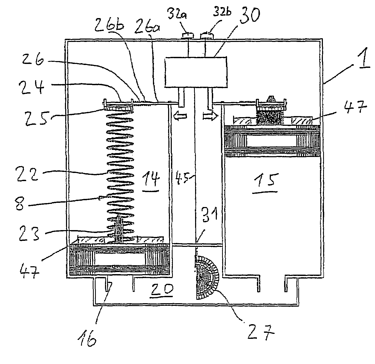
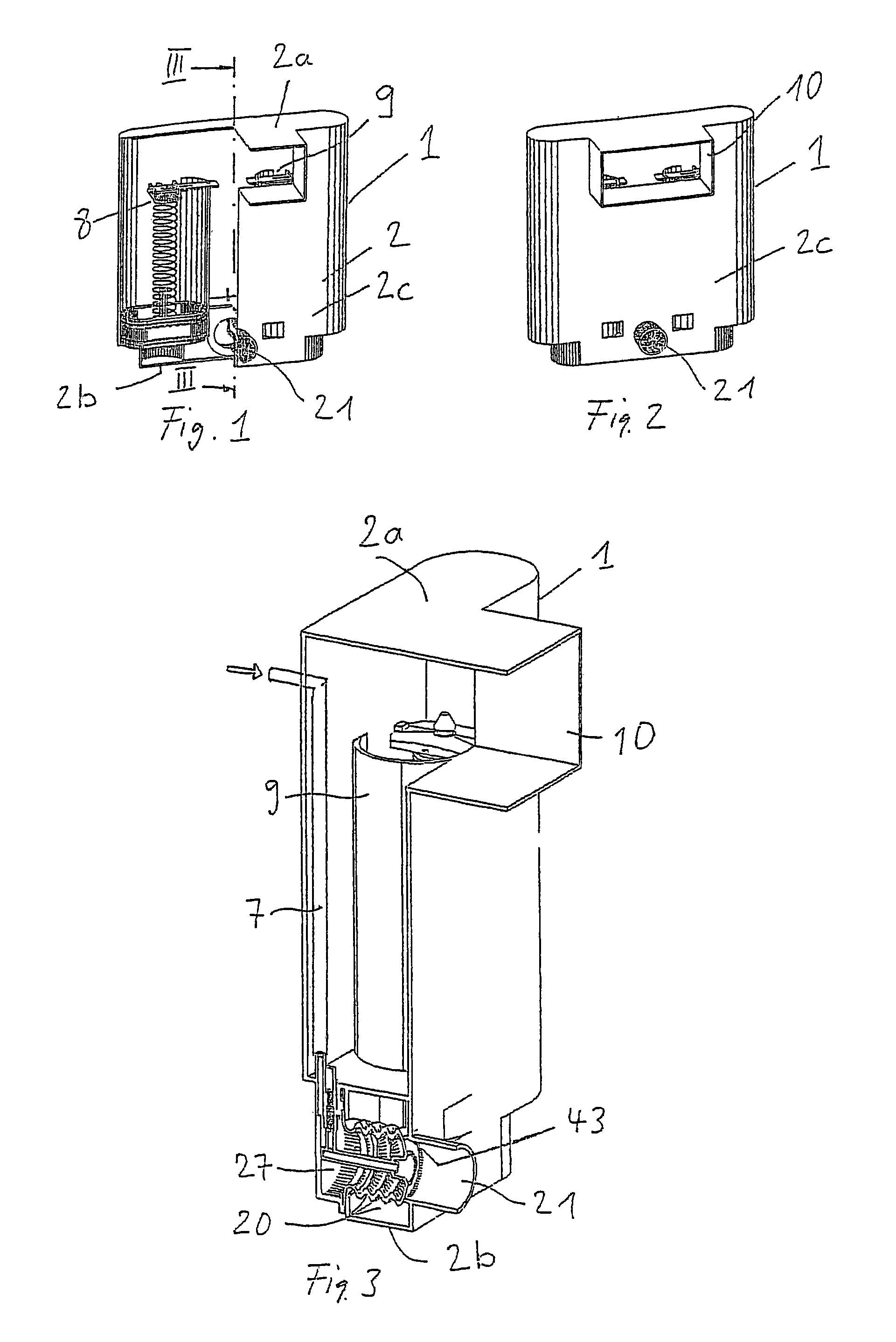
[0021]The flushing device has a flushing cistern 1, which has a cistern body 2 preferably produced from plastic. This cistern body 2 has a top wall 2a, a base wall 2b and a casing 2c. An inspection opening 10 is arranged on the front side, although it is also possible for this opening to be arranged in the top wall 2a. Located in the bottom region of the casing 2c is a discharge connector 21, which is connected to a toilet bowl (not shown here). The discharge connector 21 leads horizontally into the toilet bowl.

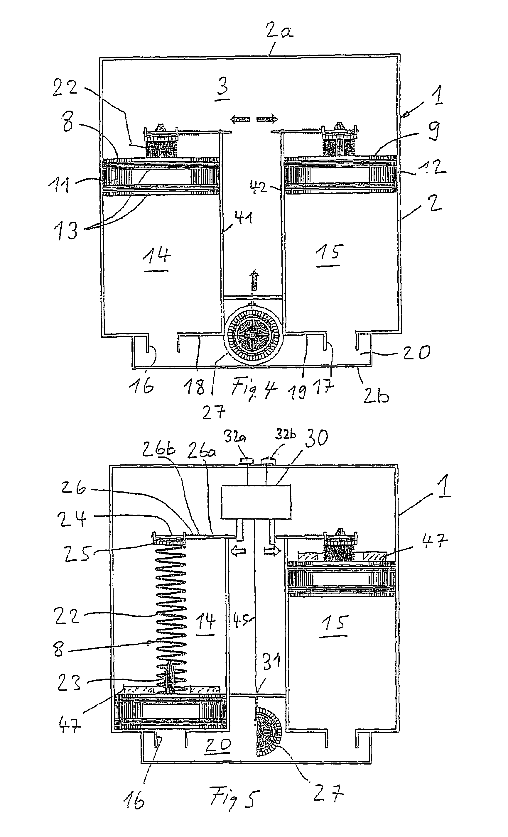
[0022]The cistern body 2 contains two pressure-cylinder units 8 and 9, which each have a respective piston 11, 12. The pistons 11 and 12 can each be displaced vertically in a respective pressure chamber 14, 15 and are sealed by sealing rings 13 in relation to a respective cylinder wall 41, 42. These walls 41 and 42 each have a respective base 18, 19, in which a respective through-passage 16, 17 is arranged. These through-passages 16 and 17 lead into a common chamber 20, in wh...


PUM


Abstract

A flushing device includes a cistern, in which at least one pressure chamber is arranged with a supply line for water and a discharge valve. At least part of the flushing water may be pressurised in the pressure chamber and may be discharged for flushing through the discharge valve. At least one pressure cylinder unit is provided, in which the flushing water may be pressurised and discharged for flushing, by means of a spring-loaded pressure piston. The pressure piston is preferably held in a starting position and may be released for a flushing execution. Should two pressure cylinder units be provided, either a partial or a complete flushing operation may be selected.

Description

BACKGROUND OF THE INVENTION[0001]1. Field of the Invention[0002]The invention relates to a flushing device for a lavatory, having a flushing cistern in which is arranged a pressure vessel, which has a feed line for water and a discharge valve and in which at least some of the flushing water can be subjected to pressure and can be discharged through the discharge valve for flushing purposes.[0003]2. Description of the Related Art[0004]Conventional flushing cisterns have, as discharge valve, a float valve which is opened, for the purpose of triggering a flushing operation, for example by the actuation of a button. The flushing cistern is arranged above the toilet bowl which is to be flushed and, when the float valve is opened, the flushing water flows, as a result of the gravitational force, through a flushing pipe into the toilet bowl. However, flushing devices in the case of which the flushing water is subjected to pressure in the flushing cistern are also known. During flushing, th...

Claims


Application Information

Patent Timeline
IPC IPC(8): E03D3/10E03D1/22
CPCE03D3/10E03D1/22
Inventor GUBELI, ALBERTVON BALLMOOS, MARIO
Owner GEBRERIT INT
Why Eureka
Try Eureka