Vehicle drive force control apparatus
a technology of drive force control and control apparatus, which is applied in the direction of motor/generator/converter stopper, dynamo-electric converter control, transportation and packaging, etc., can solve the problem of co-rotation becoming more prominent, and achieve the effect of enlarge the traveling speed region
- Summary
- Abstract
- Description
- Claims
- Application Information
AI Technical Summary
Benefits of technology
Problems solved by technology
Method used
Image

Examples
first embodiment
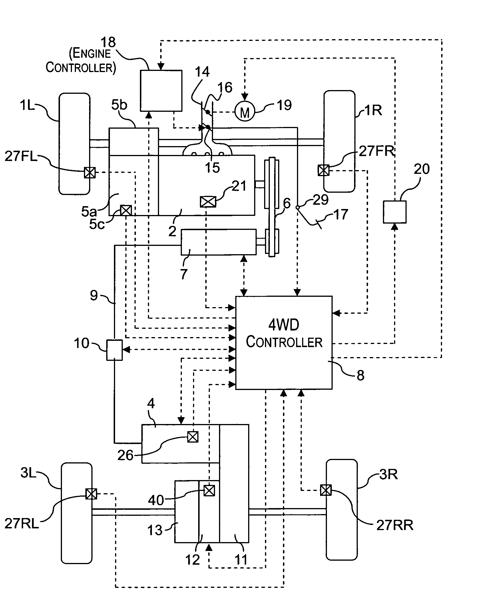
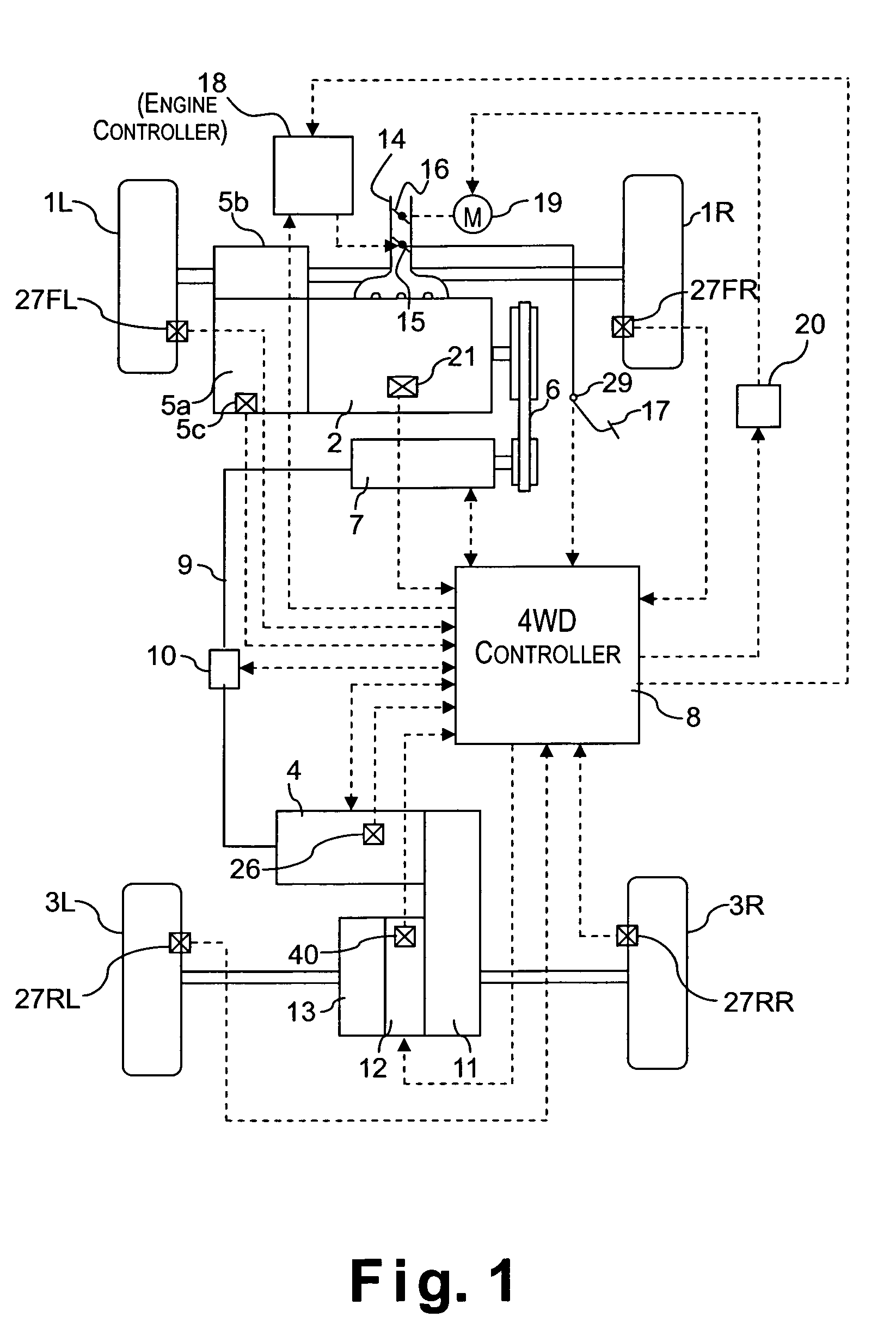
[0023]Referring initially to FIGS. 1–8, a vehicle driving force control apparatus will now be explained in accordance with a first embodiment of the present invention. As seen in FIG. 1, a four wheel drive vehicle is diagrammatically illustrated that is equipped with the vehicle driving force control apparatus in accordance with the present invention. As shown in FIG. 1, the vehicle in accordance with this embodiment has left and right front wheels 1L and 1R that are driven by an internal combustion engine or main drive source 2, and left and right rear wheels 3L and 3R that are driven by an electric motor or subordinate drive source 4, which is preferably a direct current (DC) electric motor. Thus, the front wheels 1L and 1R serve as the main drive wheels, while the rear wheels 3L and 3R serve as the subordinate drive wheels. The output torque Te of the engine 2 is delivered to the left and right front wheels 1L and 1R after passing through a transmission 5a and a differential gear...
second embodiment
[0098]Referring now to FIG. 9, a vehicle driving force control apparatus in accordance with a second embodiment will now be explained. The configuration of the vehicle used in this second embodiment is the same as the configuration of the vehicle in the first embodiment (see FIG. 1). In view of the similarity between the first and second embodiments, the descriptions of the parts or steps of the second embodiment that are identical to the parts or steps of the first embodiment may be omitted for the sake of brevity. In other words, unless otherwise specified, the rest of the configuration of the vehicle and the processing in the second embodiment are the same as the configuration of the first embodiment.
[0099]The flowchart shown in FIG. 9 is an alternative to FIG. 8, which shows the processing of the clutch control section 8D of the first embodiment. The processing of the second embodiment shown in FIG. 9 is similar to the processing of the first embodiment shown in FIG. 8 and many ...
third embodiment
[0103]Referring now to FIG. 10, a vehicle driving force control apparatus in accordance with a third embodiment will now be explained. The configuration of the vehicle used in this third embodiment is the same as the configuration of the vehicle in the first embodiment (see FIG. 1). In view of the similarity between the third and prior embodiments, the descriptions of the parts or steps of the third embodiment that are identical to the parts or steps of the prior embodiments may be omitted for the sake of brevity. In other words, unless otherwise specified, the rest of the configuration of the vehicle and the processing in the third embodiment are the same as the configuration of the prior embodiments.
[0104]The flowchart shown in FIG. 10 is an alternative to FIG. 9, which shows the processing of the clutch control section 8D of the second embodiment. The processing of the third embodiment shown in FIG. 10 is similar to the processing of the second embodiment shown in FIG. 9 and many...
PUM
 Abstract
Description
Claims
Application Information
 - R&D
- Intellectual Property
- Life Sciences
- Materials
- Tech Scout
- Unparalleled Data Quality
- Higher Quality Content
- 60% Fewer Hallucinations
Browse by: Latest US Patents, China's latest patents, Technical Efficacy Thesaurus, Application Domain, Technology Topic, Popular Technical Reports.
© 2025 PatSnap. All rights reserved.Legal|Privacy policy|Modern Slavery Act Transparency Statement|Sitemap|About US| Contact US: help@patsnap.com