
Method and device for regulating a wind machine

a wind machine and wind power technology, applied in the direction of motors, dynamo-electric machines, optimising machine performance, etc., can solve the problems of wind power machine racing, deterioration/or the bearing of the rotary assembly, and general inacceptable variations

Inactive Publication Date: 2006-08-22
JEUMONT
View PDF13 Cites 80 Cited by
  • Summary
  • Abstract
  • Description
  • Claims
  • Application Information

AI Technical Summary

Benefits of technology

[0041]according to a second embodiment of the invention, in a second phase of operation of the wind machine, when the wind speed is higher than a second threshold value the maximum speed of rotation of the rotary assembly of the wind machine is regulated in such a way as to maintain the power of the wind machine at a fixed value and, preferably, at the maximum power value acceptable by the wind machine;
[0042]in this case, preferably, when the value of the wind speed is lower than the second threshold value the speed of rotati

Problems solved by technology

However, the drawbacks of a direct connection between the rotating part of the wind machine and the rotor of the alternator are that the alternator must be able to operate in a satisfactory manner at a low speed of rotation and that the variable atmospheric conditions in which the wind machine functions, in particular the wind speed, can bring about variations in the electrical parameters of the current supplied by the wind machine to an electric network, these variations being generally unacceptable.
However, in the French patent application there is no description of means permitting regulation of all the operating parameters of the wind machine, whether these parameters relate to the electrical operation of the alternator or are constituted by the speed of rotation of the rotary assembly of the wind machine.
A first problem which is posed within the framework of operation of the wind machines relates to the protection of the rotary assembly comprising the blades and the hub of the wind machine when the wind is very strong and reaches speeds which are likely to bring about racing of the wind machine and deterioration of the rotary assembly and / or the bearings of this rotary assembly.
The wind machines must be produced in such a way as to ensure disengagement of the rotating part when the wind speed exceeds a certain level; the performance of the blades of the rotary assembly then becomes very poor and racing is avoided.
The “stall” system has the drawback of being definitely adjusted when the mounting of the blades on the hub of the rotary assembly has been ensured, as the disengagement is always effected for a predetermined wind speed.
Such operations are ponderous and are reflected in operational losses both in terms of supply and sale of electric current.
However, each of these two operating speeds is only adapted to one wind speed and, outside these ideal conditions, the power output of the wind machine is dissipated all the more as the conditions deviate from the ideal operating conditions.
Another drawback of the wind machines in which the blades have a fixed setting and which operate according to the fixed-speed “stall” system is that it is necessary to reach the nominal speed of rotation of the wind machine before connecting the generator to the network in order to avoid connection in conditions which are unacceptable for the network.
However, such systems are extremely fragile due to the mounting of the blades by means of a bearing and the use of a chain for regulation of the setting angle.
Therefore the orientation of the blades is not always at the ideal value necessitated by the operating conditions.
For this reason, in certain phases insufficient power is recovered or, on the contrary, excessive power is recovered, which brings with it drawbacks in the operation of the mechanical or electrical transmission of power.
Following the stoppage, it is necessary to provide a procedure for restarting so that this mode of operation with stopping of the wind machine is reflected in a loss of production and fatigue of the mechanical elements of the wind machine and in particular of the mechanical brake used for stopping and of the blades.
The power of the wind machine is not perfectly controlled, and for this reason it is necessary to provide oversizing of the wind machine in order to meet all the demands, which involves additional costs.

Method used


Image

  • Method and device for regulating a wind machine
  • Method and device for regulating a wind machine
  • Method and device for regulating a wind machine

Examples


Embodiment Construction

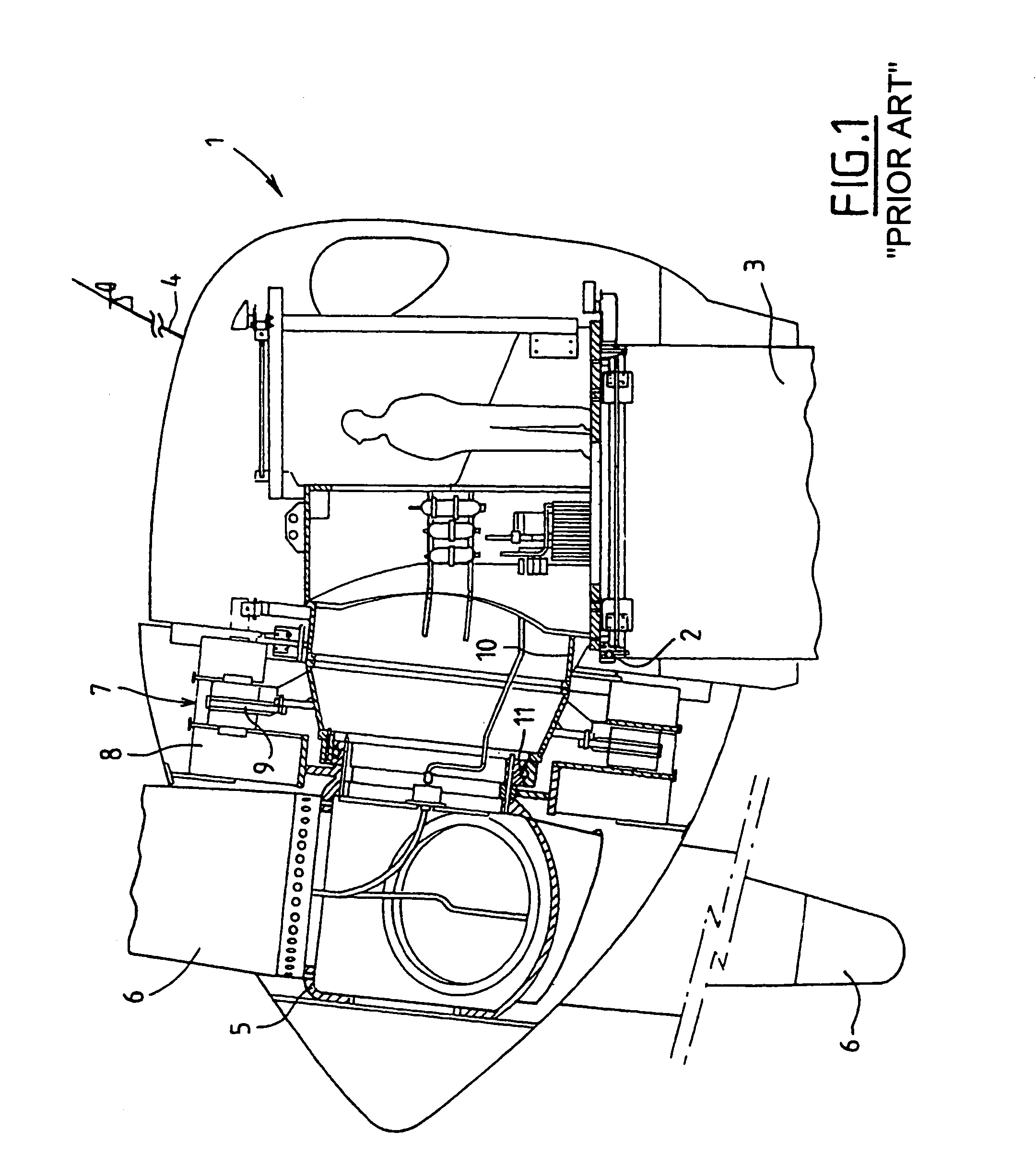
[0053]An antenna 4 bearing a wind telltale permits control of a motor for orientation of the nacelle 1 of the wind machine about the vertical axis of the mast 3 in order to orient it relative to the direction of the wind at any moment.

[0054]The nacelle 1 of the wind machine bears the rotary assembly of the wind machine which includes in particular a hub 5 on which three blades 6 having a profiled section are fixed in a rigid manner.

[0055]The rotating part of the wind machine comprising the hub 5 and the blades 6 ensures that the rotor 8 of an electric current generator 7 is set in rotation, this electric current generator having a stator 9 fixed on a structural part 10 of the nacelle 1 integral with a platform mounted so as to rotate on the end of the mast 3 by means of the horizontal bearing 2.

[0056]The rotor 8 and the stator 9 of the alternator 7 are produced in discoid form, the rotor 8 having two rotor elements placed on either side of the stator, each of the rotor elements havi...


PUM


Abstract

A method and corresponding apparatus for regulating a system that produces electric power, the system including an electric alternator having a rotor integral with a rotating part of a wind machine to form a rotary assembly, and a power electronics module, the method including the steps of: producing an alternating current at output terminals of the alternator; converting the alternating current produced by the alternator into modulated pulses of direct current. Alternating electric current produced by the alternator is regulated by controlling the speed of rotation of the rotary assembly by resisting torque imposed by the alternator in response to modulating the pulses of continuous current produced by the converted the alternating current.

Description

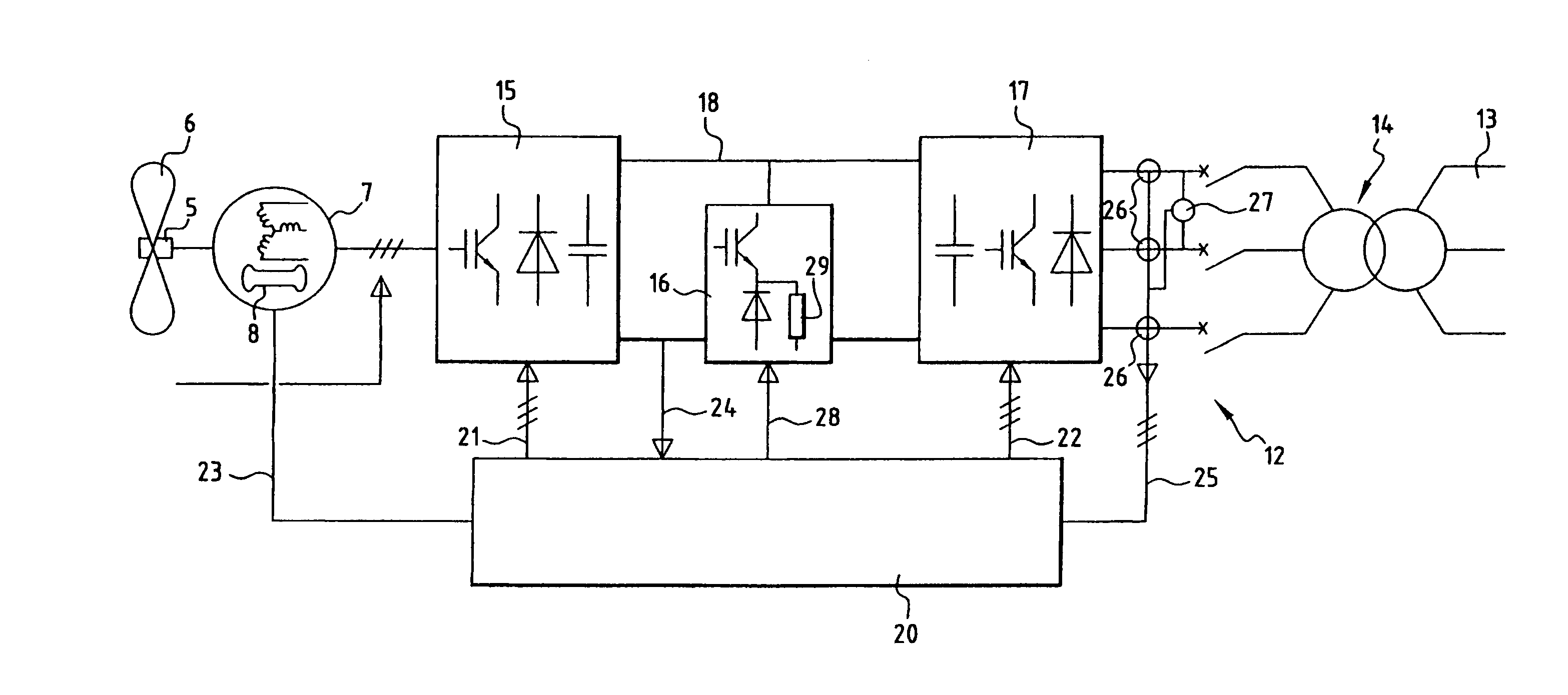
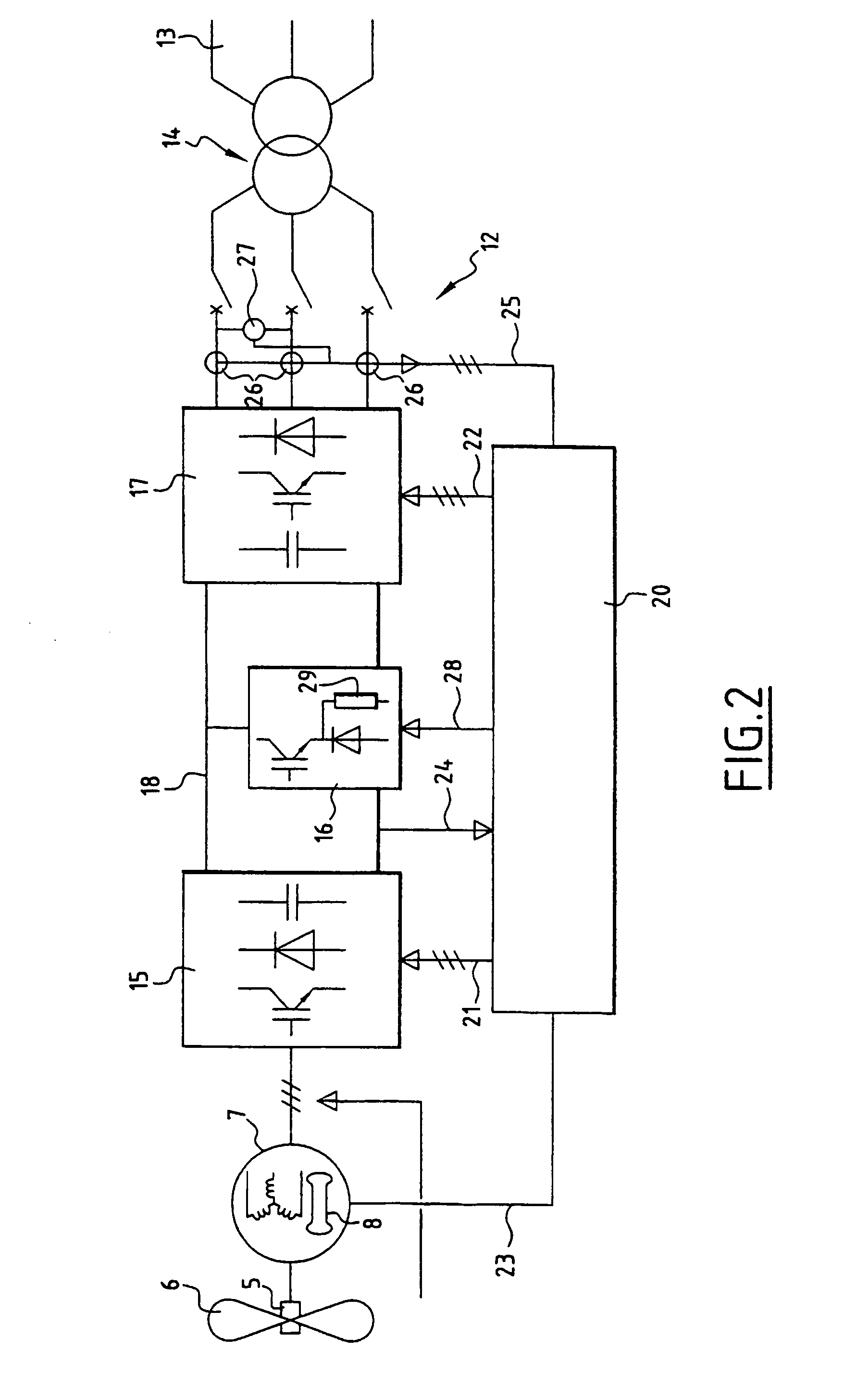
FIELD OF THE INVENTION[0001]The invention relates to a method of regulating operating parameters of an installation for producing electric power comprising a wind machine and a device for carrying out the method.BACKGROUND OF THE INVENTION[0002]Installations are known for producing electric power from wind power which comprise an alternator of which the rotor is driven by a rotating part of a wind machine having a hub and blades fixed on the hub.[0003]In particular wind machines have been proposed in which the rotating part is connected directly to the rotor of the alternator without intermediate mechanical transmission. Such wind machines have the advantage of a greater mechanical simplicity, the rotating assembly comprising the rotating part of the wind machine integral with the rotor of the alternator being mounted so as to rotate on the structure of the wind machine via at least one block which may consist of one single bearing, in an advantageous embodiment.[0004]Furthermore, t...

Claims


Application Information

Patent Timeline
IPC IPC(8): H02P9/00F03D7/00F03D9/25
CPCF03D9/002Y02E10/725F05B2270/20F03D9/25F03D80/70Y02E10/72
Inventor CANINI, JEAN-MARCMILET, YVESBRUTSAERT, PATRICK
Owner JEUMONT
Learn More