
Transmission

a technology of coupling sleeves and transmission lines, applied in the field of transmission, can solve the problems of large loss of time, large time consumption, and inability to select the shift process simultaneously, and achieve the effect of consuming a great deal of time, prolonging the shift process, and maximising performan

Inactive Publication Date: 2006-08-22
SCHAEFFLER TECH AG & CO KG
View PDF10 Cites 28 Cited by
  • Summary
  • Abstract
  • Description
  • Claims
  • Application Information

AI Technical Summary

Benefits of technology

[0028]An advantage of the present invention is that with the final actuation mechanism, the primary actuation elements can immediately be brought into the neutral position after the shift of a gear in a power branch and need not remain in the shift passageway of the engaged gear. Moreover, in addition to driving technical aspects, safety technical aspects, for example overspeed protection for a new gear, can also be taken into consideration. The following pre-selection strategies can be advantageous:
[0029]Engaging the next higher gear: Following a shift process, that is, when the clutch applies torque to the current drive gear of a power branch, the torque will be engaged with the current drive gear and the other, load-free power branch. If there is no higher gear, the highest gear in that branch is engaged. In that way, overspeed protection is ensured while shifting torque to that power branch. A previous, still-engaged gear is disengaged with that shift process by means of the secondary actuation element. The clutch in that power branch remains disengaged until a shift requirement for the engaged gear is triggered by the control logic.
[0030]Pre-selection of a lower gear: After the next higher gear is engaged in the load-free power branch following the above-described routine, the transmission actuator is positioned in the neutral position without again disengaging the engaged gear. Thereafter, a positioning in the selection direction occurs in a shift passageway of a gear of a gear ratio, which is preferably smaller than that of the current drive gear and that of the gear engaged in the load-free power branch. For example, it is particularly advantageous for the gear that is calculated by the controller logic, upon a kick-down by the driver, as a target gear for maximal performance, whereby that gear can be changed during operation in that transmission position, whereupon the position of the selection actuator can also be changed. In manual operation of the vehicle, in which the driver actively selects the next drive gear step, the selected shift passageway can be that of the gear that has the next smaller gear ratio relative to the current drive gear. In a further variant for rapid acceleration of the vehicle, for example for an actuation of the accelerator pedal above a set threshold, the shift passageway can be selected with the gear into which the vehicle would shift if the vehicle were to continue to be constantly operated at the current speed, for example, a gear with higher gear ratio (overdrive) for economical operation of the vehicle. It should be understood that the shift movement is tracked corresponding to the current driving situation, and thereby the current gear alternative to the gear engaged on the load-free power branch can always be kept available using a simple shift / disengage motion.
[0031]Transmissions according to the concept of the invention can also be designed according to other aspects in which it need not be considered that the gears, which are arranged adjacent with reference to their reduction in known arrangements, for example, gears 1 and 2 in one shift passageway can be arranged to be adjacent to gears 3 and 4 in the adjacent shift passageway because the new gear to be engaged can be engaged by means of the primary actuation element and the engaged gear can be disengaged using a secondary actuation element without additional selection processes. To accelerate the shift times, the new gear to be engaged can already be pre-selected as long as the engaged gear is still engaged. The shift movement can already be initiated, while the engaged gear has not yet been disengaged, so that the transmission shift actuator can undergo a startup time before the shift process and need not be started from standstill, since, as is well known, starting up from a standstill consumes a great deal of time and delays the shift process.
[0032]It can also be advantageous for obtaining especially rapid shift processes to pre-select the likely following gear with a single branch transmission having a transmission input shaft and a transmission output shaft. The following pre-selection criteria can be advantageous as a function of the driving situation or the position of the selector lever of the transmission without a shift command to another gear having already taken place:
[0033]The selector lever is in the drive (D) position, or in manual operation mode (M; the individual gears are actuated by the driver, for example by means of a Tiptronic control), a forward gear is engaged. As long as the vehicle travels in this driving mode with a speed above a threshold to be established for each engaged gear, the accelerator position or longitudinal acceleration of the vehicle is evaluated to pre-select the next higher or next lower gear of the engaged gear. When the vehicle is accelerating, the next higher gear is pre-selected, when the vehicle slows down it is the next lower gear. In order to avoid unnecessary adjustment movements, a hysteresis band can be provided in the pre-selection routine. In the highest gear, the next lower is pre-selected. In gear 1, gear 2 can be pre-selected beginning with a speed threshold to be specified, below that the neutral position of the transmission will be pre-selected.

Problems solved by technology

Moreover, the transmission ratio steps that can be shifted by the same coupling sleeve cannot be selected simultaneously.
In the event that selection of a shift passageway is necessary, the shift process turns out to be relatively long, which can be disturbing and relevant to safety, especially with automated shift transmissions with tractive force interruption, for example during passing, turning, and the like.
In the event that now suddenly nonetheless a downshift into second gear is to take place, the fourth gear must first be disengaged and then the second gear must be engaged, which in particular causes a very great loss of time if the second and fourth gears must be shifted by different coupling sleeves.
Furthermore, a negative situation can arise for a transmission shift in which, with an open power branch, more than one transmission ratio step is engaged, which represents a very great safety risk because as soon as that branch is tied into the torque flow, several transmission ratio steps with different transmission ratios become operative, which can lead to the transmission becoming blocked or even destroyed.
Nonetheless, shifts are only possible sequentially.

Method used


Image

  • Transmission
  • Transmission
  • Transmission

Examples


Embodiment Construction

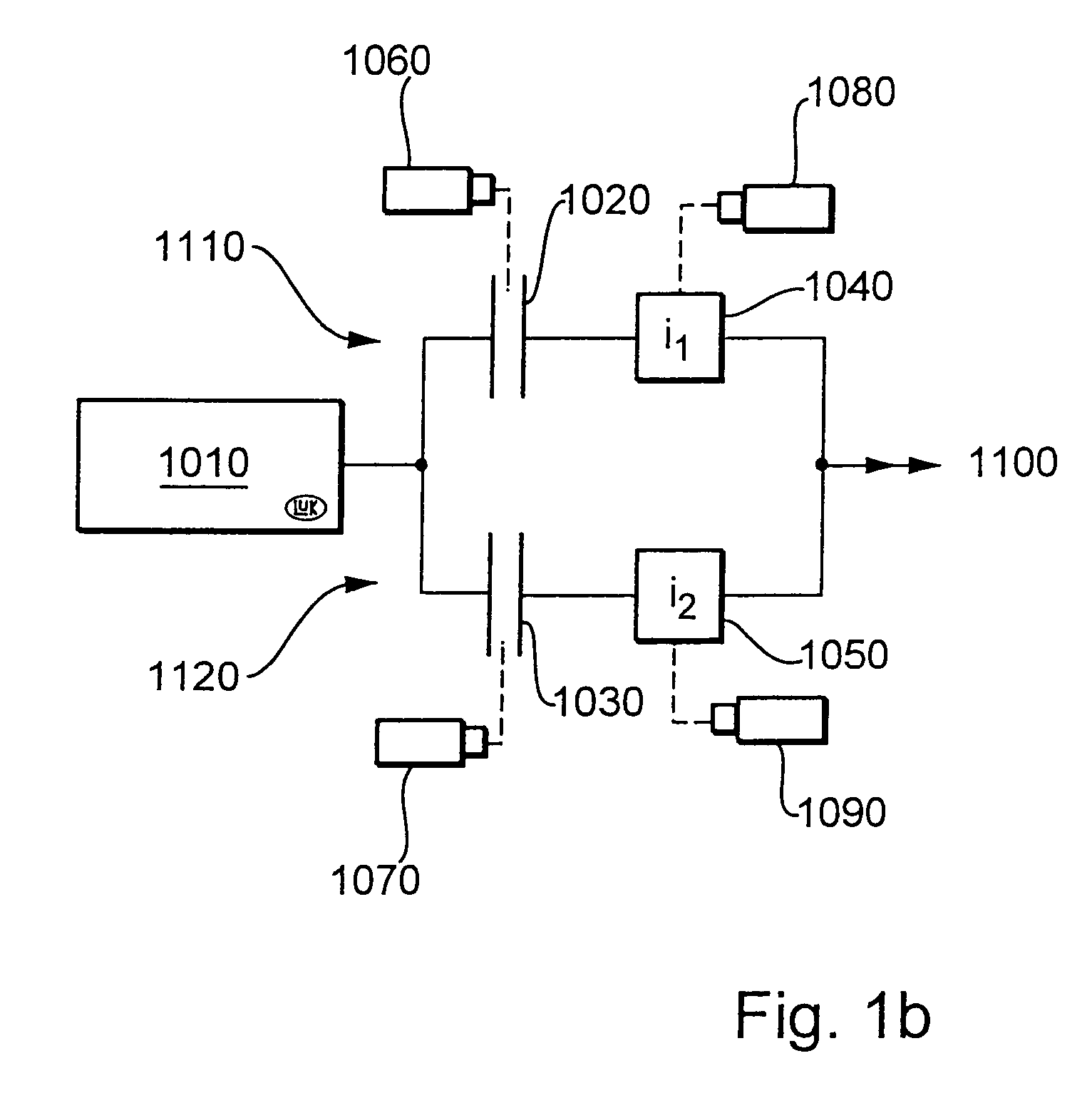
[0077]FIG. 1a shows schematically and by way of example a motor vehicle 1 in which the invention can be utilized especially advantageously. The clutch 4 is presently arranged in the power flow path between drive motor 2 and transmission device 6. Appropriately a divided inertial mass 7 is arranged between drive motor 2 and the clutch 4, the component masses of which are rotatable relative to each other and are in line with a spring damper arrangement, whereby the vibration characteristics of the drive train are substantially improved. Preferably, the invention is combined with a damping apparatus for absorbing or offsetting rotary impulses, or equipment for compensating for rotary impulses, or rotary impulse-diminishing apparatus, or apparatus for damping vibrations, such as are particularly described in published German patent applications DE OS 34 18 671, DE OS 34 11 092, DE OS 34 11 239, DE OS 36 30 398, DE OS 36 28 774 and DE OS 37 21 712 of the assignee, the disclosures of whic...


PUM


Abstract

A power transmission for a motor vehicle. The transmission includes a plurality of transmission ratio steps defined by pairs of gear carried on parallel shafts, and final output mechanisms for engaging desired transmission ratio steps. The final output mechanisms are operable for controlling the engagement of respective transmission ratio steps to minimize tractive force interruption by allowing rapid gear changes to be effected to reduce the times between shifts of gears. By sensing accelerator pedal position and vehicle speed a new transmission ratio step to be subsequently engaged can be pre-selected while an engaged gear remains engaged.

Description

CROSS-REFERENCE TO RELATED APPLICATION[0001]This application is a continuation of international application serial number PCT / DE02 / 00577, filed on Feb. 18, 2002, the entire contents of which are hereby incorporated by reference.BACKGROUND OF THE INVENTION[0002]1. Field of the Invention[0003]The invention relates to a transmission, especially for a motor vehicle. More particularly, the invention relates to a transmission that has a plurality of sets of gears forming transmission ratio steps, wherein the gear sets are each formed by one gear that is non-rotatably carried on one shaft and by an idler gear connectable with another shaft, whereby transmission ratio steps can be selected, and in which an idler gear is connected with its associated shaft by an output element that is part of a final output mechanism that is actuated by a final actuation mechanism, whereby the selection sequence of the transmission ratio steps is not established in the final actuation mechanism.[0004]2. Desc...

Claims


Application Information

Patent Timeline
IPC IPC(8): F16H59/00F16H61/00F16H63/00B60K1/02F16H63/32B60K6/24B60K6/26B60K6/36B60K6/387B60K6/40B60K6/48B60K6/54B60K6/547B60W10/02B60W10/08B60W10/10B60W20/00F16H3/00F16H3/093F16H3/097F16H3/12F16H61/04F16H61/688F16H63/20F16H63/22F16H63/30F16H63/36
CPCB60K6/24B60K6/36B60K6/387B60K6/40B60K6/48B60K6/547F16H61/688F16H63/206F16H63/22B60K6/26F16H2063/3073B60Y2400/428F16H3/006F16H3/097F16H3/126F16H2003/123F16H2061/0411F16H2061/0422F16H2063/025F16H2306/14F16H2306/44F16H2306/48F16H2306/52Y02T10/6221Y02T10/6295F16H2063/202Y10T74/19251Y10T74/19279Y02T10/62F16H63/20
Inventor NORUM, VIGGO L.LEIN, LARSHUSEBY, GEIRHIRT, GUNTERBERGER, REINHARDBUNDER, CARSTENSEREBRENNIKOV, BORISMETZGER, JORGFISCHER, ROBERTPOLLAK, BURKHARDAHNERT, GERD
Owner SCHAEFFLER TECH AG & CO KG
Learn More