
Device for supporting a horizontal guided glass strand

a technology of horizontal guided glass and glass strands, which is applied in the direction of glass forming apparatus, glass making apparatus, manufacturing tools, etc., can solve the problems of abrasion, contamination of the glass strand surface, and further cooling of the glass strand to prevent and reduce the risk of deformation. , the effect of preventing the risk of deformation

Inactive Publication Date: 2006-08-22
SCHOTT AG
View PDF17 Cites 1 Cited by
  • Summary
  • Abstract
  • Description
  • Claims
  • Application Information

AI Technical Summary

Benefits of technology

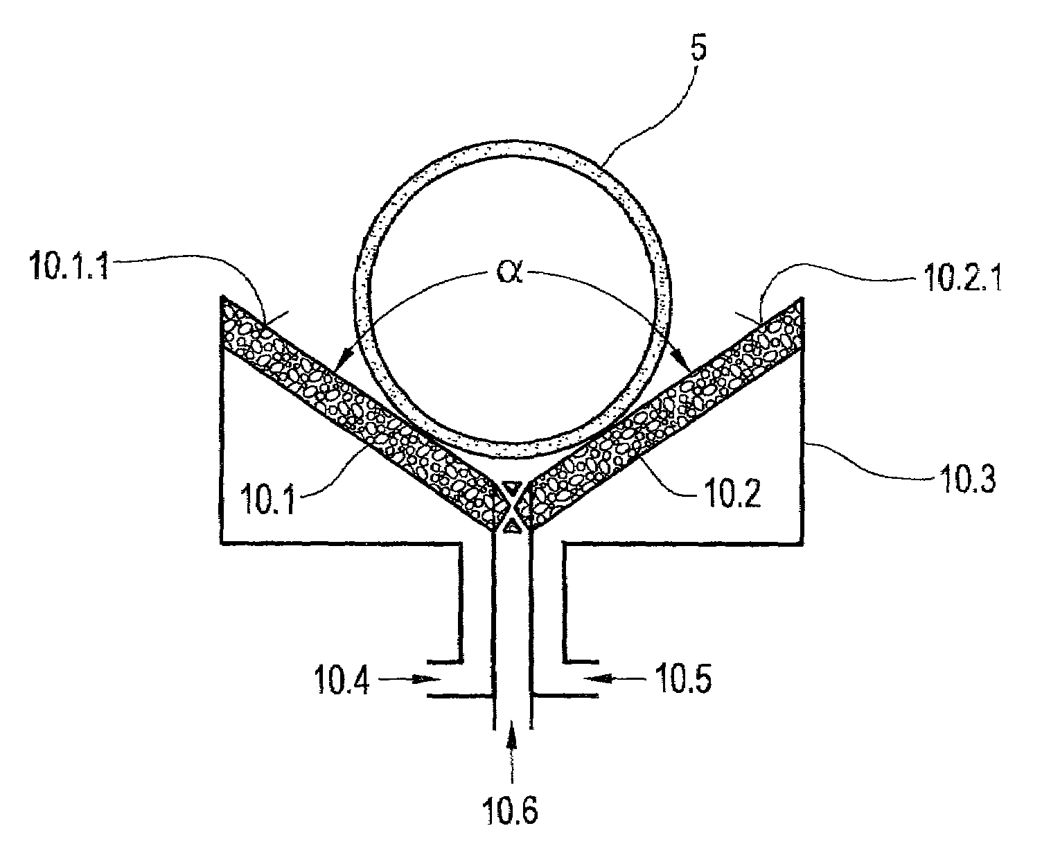
[0013]The invention is based on the task to design a device of the initially described kind in such a manner that a glass strand—solid or hollow—originating from a continuous casting unit, is horizontally guided and supported, without having contact with a firm environment, so that damage of the glass strand and / or wear of the supporting blocks are avoided, with good dimensional accuracy of the glass strand as well as with low capital investment cost and low operating cost.
[0015]Thus the difficulties connected with rollers or firm supports, like the local extraction of heat at support points and the risk of deformation, are eliminated. Contrary to the rollers or firm supports the carrying force will transfer over a substantially larger area to the tubing strand, which prevents the risk of deformation. Moreover, the heat dissipation from the glass strand is homogenized, since no local contact between the glass strand and the supporting device takes place. The heat dissipated by the supporting gas is removed from the glass strand over a large surface area.
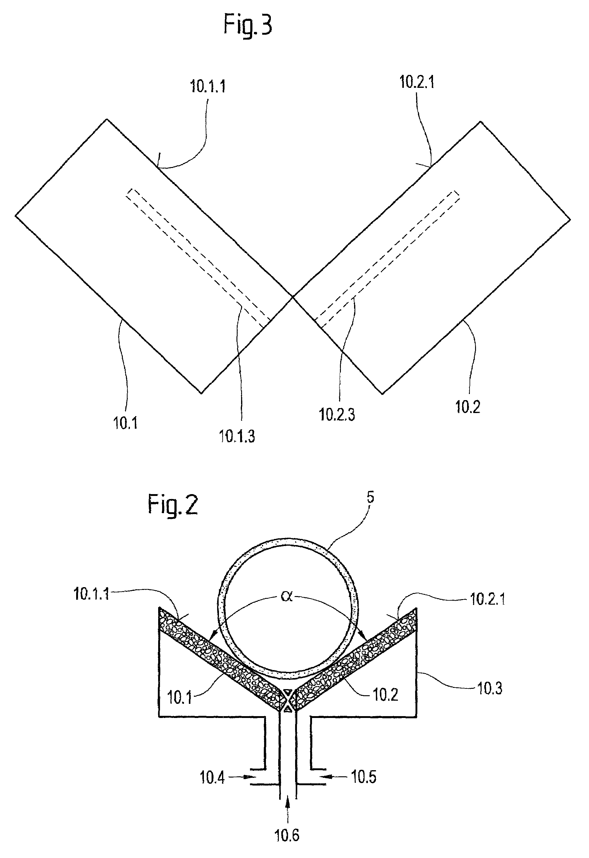
[0016]An interesting variation of the invention consists of providing the diaphragm bodies with channels for passing the compressed gas and to locate the channels at a certain distance to the gas emerging area—called from now on “supporting area”—generally parallel to the supporting area. Thereby it is possible to use diaphragm bodies made from a material with relatively low strength and to design the diaphragm bodies relatively thick-walled, so that on the one hand there is no risk of fracture, and that however on the other hand the compressed gas has to cover only a short distance from the channel to the supporting area, so that the pressure of the compressed gas can be relatively low.

Problems solved by technology

The small supporting surface, which the rollers offer to the glass strand, causes the glass strand (especially in its hot area) to be deformed during transport over the rollers, which in return causes an impairment of its dimensional accuracy and especially problems with ovalness.
The nonuniform heat distribution over the circumference of the glass strand leads with further cooling to distortion and bending of the glass strand.
In addition, the contact to the rollers transfers dust and dirt on the glass strand.
This abrasion creates contaminations on the glass strand surface.
During the progressive wear the occurrence of the scratches created by the supporting device increases, until the rollers and blocks must be exchanged after some time.
This leads to a mutual impairment.
On the one hand scratches can develop on the exterior of the glass tube, on the other hand material wear of the supporting device takes place, especially if a soft material such as graphite is used for it.
However, lateral contact of the glass strand with the walls cannot always be prevented, so that in these cases the surface of the glass strand is damaged or contaminated.
However, the necessary airflow for supporting the glass strand would be so large, that the nozzles would cause an inadmissibly high noise level.
Furthermore there is the risk that the gases impacting the glass strand surface with high speeds deform the glass strand especially in its hot area.
Besides, this principle is not economical due to the high costs of compressed air.

Method used


Image

  • Device for supporting a horizontal guided glass strand
  • Device for supporting a horizontal guided glass strand
  • Device for supporting a horizontal guided glass strand

Examples


Embodiment Construction

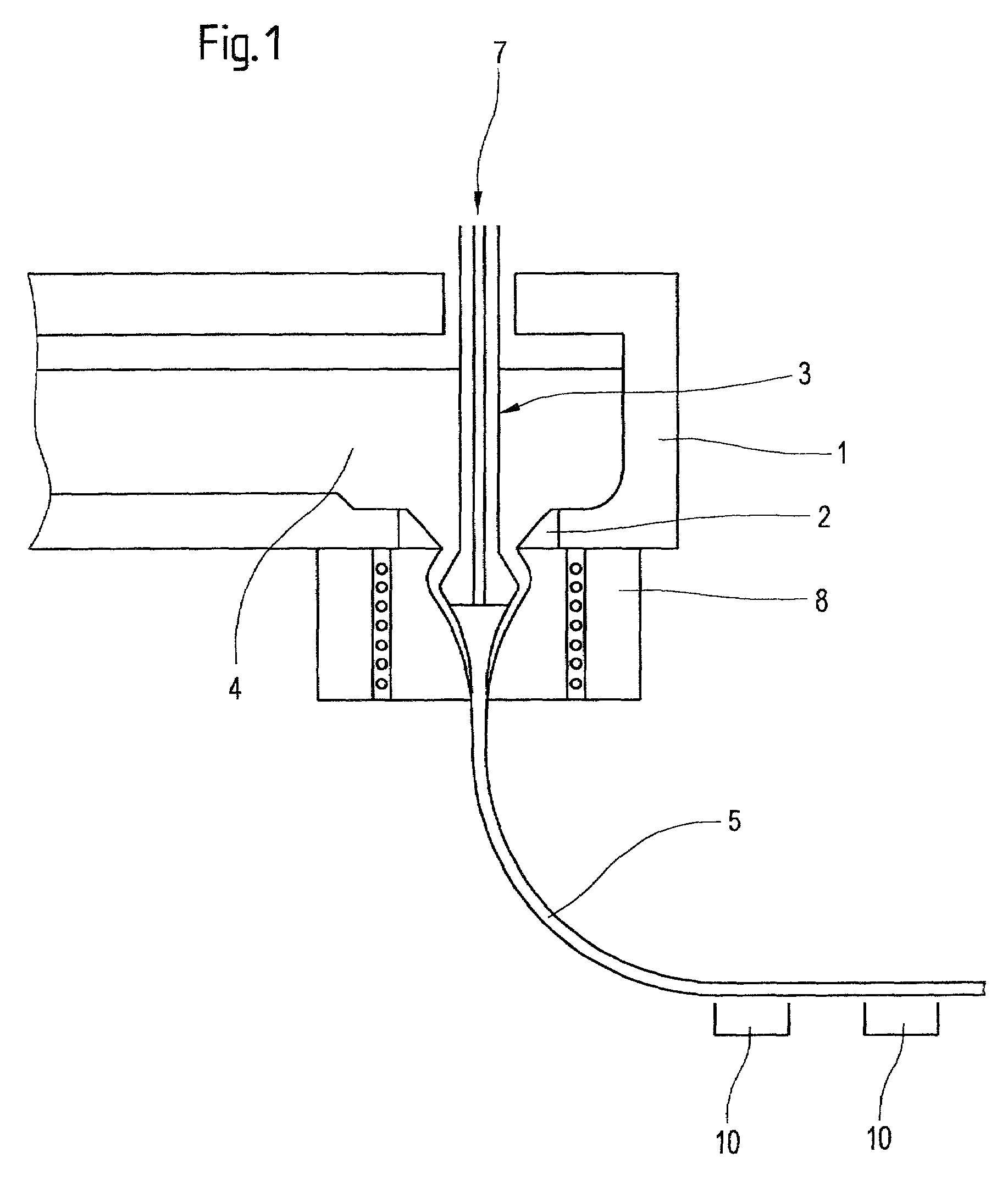
[0021]The device represented in FIG. 1 exhibits a feeding head 1. At the base of the feeding head 1 sits a discharge ring 2. Centered in this ring is the tube-drawing needle 3. The needle consists of a long shank, whose lower end is extended downwards conically. This cone, the pinhead, is scarcely below the discharge ring. The needle shank is hollow for guiding the gas atmosphere 7 (drilled hole), so that the gas atmosphere can be blown through. The needle can be traversed in horizontal and vertical directions.

[0022]The molten glass mass 4 flows through the annular gap between needle 3 and ring 2 and expands over the conical pinhead. From the edge of the pinhead, the tear-off edge, it flows downwards and forms into a bulb. The created hollow strand 5 is bent in the horizontal direction before solidifying while hanging freely and pulled off over supporting blocks 10 according to the invention with a drawing machine.

[0023]The gas pressure of the gas atmosphere 7 can be regulated, so t...


PUM

PropertyMeasurementUnit
diametersaaaaaaaaaa
temperatureaaaaaaaaaa
gravityaaaaaaaaaa

Abstract

The invention concerns a device for supporting a horizontal guided, continuous glass strand;with a number of supporting blocks, which each exhibits a supporting area, facing the glass strand;the individual supporting block in the area of the supporting area is made from a porous, gas-impermeable diaphragm body;the diaphragm body is connected to a source of compressed gas for conveying gas through the supporting area.

Description

BACKGROUND OF THE INVENTION[0001]The invention concerns a device for supporting a horizontal guided, continuous glass strand.[0002]The Danner-Technique and the Vello-Technique are used for the industrial production of glass rods and glass tubes up to diameters of approximately 100 mm. With the Danner-Technique the glass flows from a nozzle on top of a rotating tilted pipe, through which, in the case of producing tubes, a glass is blown and a glass strand is pulled off continuously from the tip. With the Vello-Technique a ring nozzle, through whose center the glass is blown for the tubing production, creates the glass strand.[0003]Tube drawing techniques have become known for example from DE 100 54 804 A1.[0004]With the usual techniques for the production of glass rods or glass tubes, the hot and ductile glass strand is directed into the horizontal level, cooled down over the length of the drawing bench and finally separated into sections of the desired length. The glass strand, whic...

Claims


Application Information

Patent Timeline
Patent Type & Authority Patents(United States)
IPC IPC(8): C03B35/26C03B17/04C03B40/04
CPCC03B17/04C03B40/04C03B35/26
Inventor DICK, ERHARDFISCHER, ERICHFUCHS, ROLANDRIEDEL, MARKUSLANGE, ULRICHLANGSDORF, ANDREASKUNERT, CHRISTIAN
Owner SCHOTT AG
Learn More