
Universal point of contact identifier system calling device and method

Active Publication Date: 2006-08-15
AYMAN
View PDF13 Cites 19 Cited by
  • Summary
  • Abstract
  • Description
  • Claims
  • Application Information

AI Technical Summary

Benefits of technology

[0007]The controller is configured to control the communication unit to transmit an initiation signal over the network to the server to establish the communication link between the calling device and the server, where the initiation signal is based on the connection code. The controller is further configured to control the communication unit to transmit a connection request signal over the network to the server in response to establishing the communication link, where the connection request signal includes the identifier. Transmission of the connection request signal facilitates an automatic connection between the preferred end unit of the caller and the preferred contact device of the call recipient over the telephone network. Optionally, the calling device may also be configured to receive information about a subscriber (e.g., a preferred physical address) from the server and display such information via a display in response to transmission of the connection request signal to the server.
[0008]The universal point of contact identifier system calling device solves the problem of easily entering a universal point of contact (UPOC) identifier such as an email address. Such a calling device allows a caller to originate calls to entities registered with a universal point of contact identifier system (UPOCIS) by using a universal point of contact (UPOC) identifier.

Problems solved by technology

While the universal point of contact identifier system solves the problem of consolidating a person's points of contact to a single identifier, such as an email address, the problem of reliably and conveniently facilitating entering such an identifier remains.
For example, entry of an email address consisting of letters, numbers and other symbols such as the “@” symbol, is difficult and confusing, if not impossible using a conventional touch-tone telephone keypad.

Method used


Image

  • Universal point of contact identifier system calling device and method
  • Universal point of contact identifier system calling device and method
  • Universal point of contact identifier system calling device and method

Examples


Embodiment Construction

[0013]Various embodiments of the present invention are described below with reference to the above drawings, in which like reference numerals designate like components.

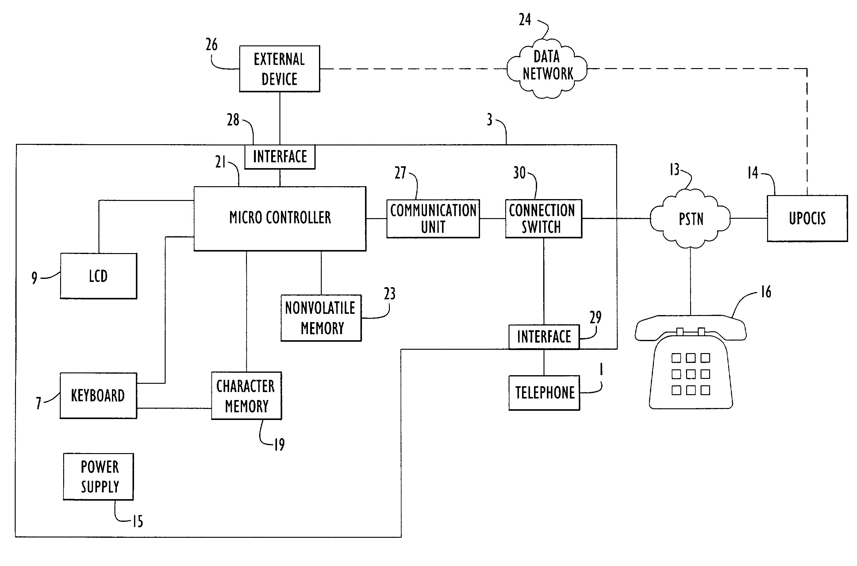
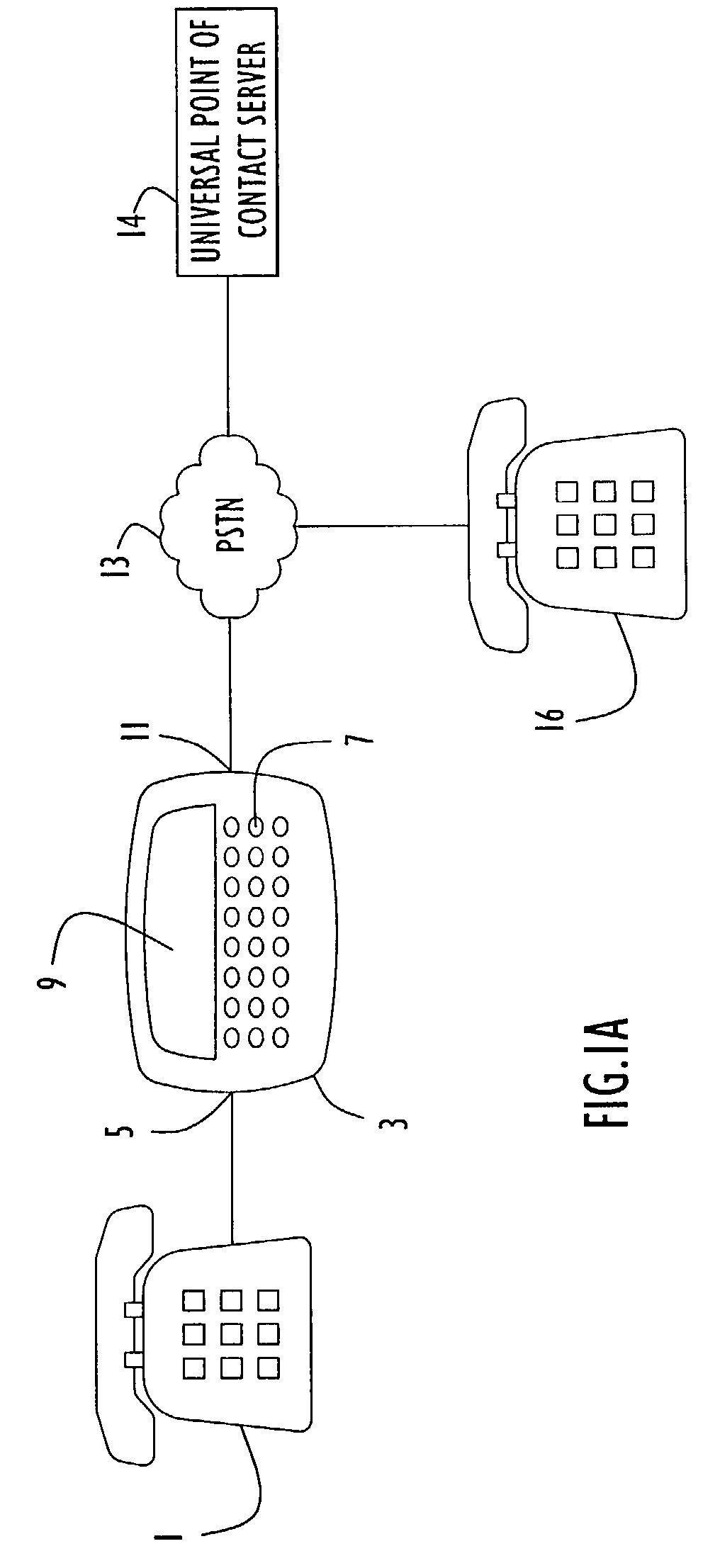
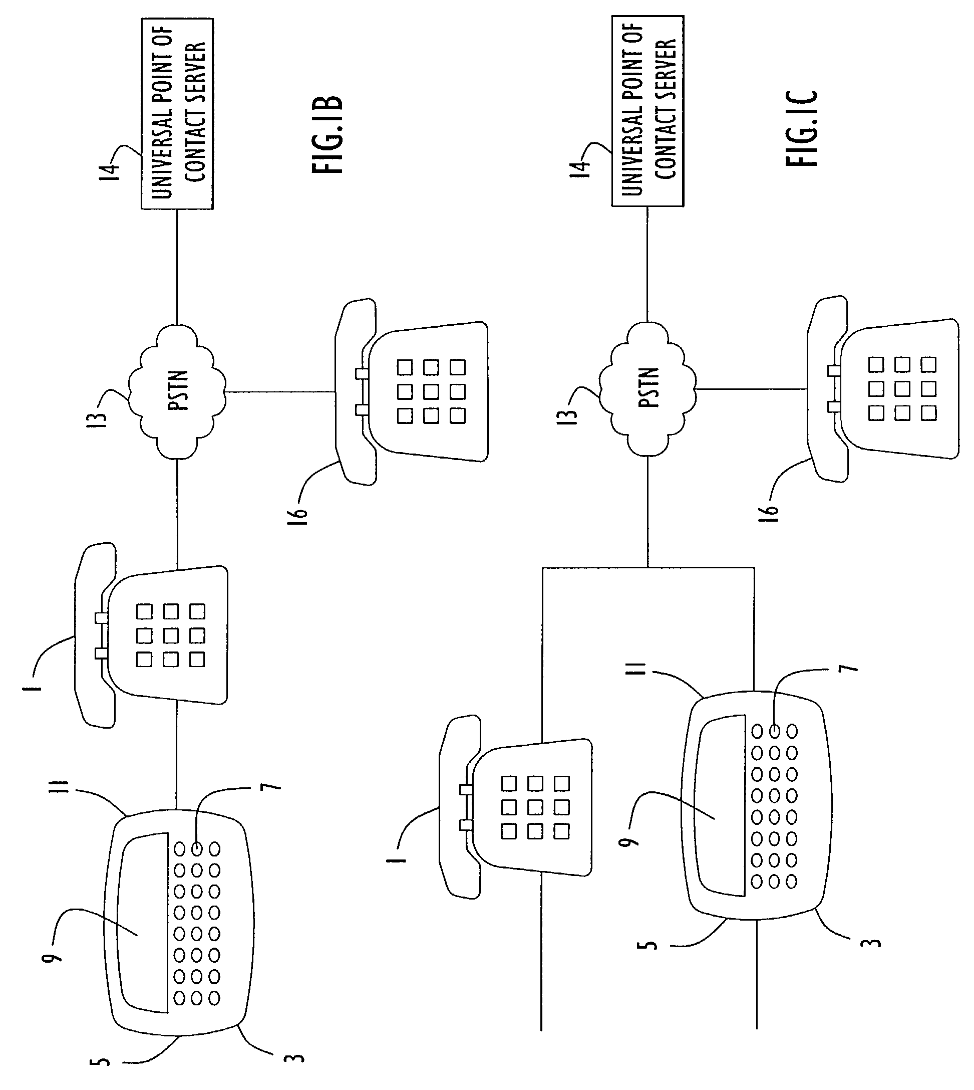
[0014]Telephone systems that employ a universal point of contact calling device are shown in FIGS. 1A–1D. The universal point of contact device includes an alpha-numeric keyboard, a display, a circuit, such as a modem or appropriately programmed digital signal processor for making a telephone call and transmitting and receiving digital data, an inline telephone connection, a power supply, a micro-controller, a character memory, and a non-volatile memory unit.

[0015]Referring to FIG. 1A, a telephone 1 is connected to a universal point of contact calling device 3 by way of a connector unit 5, an example of which is a RJ-11 receptacle. Calling device 3 includes a keyboard 7 and a display unit 9, such as a liquid crystal diode (LCD) or any other suitable display, that provides visual feedback to the caller. Both the keyboa...


PUM


Abstract

A universal point of contact identifier system calling device facilitates a connection between a caller and a call recipient over a telephone network by communicating with a universal point of contact identifier system server. The calling device includes a keyboard, a display, a circuit to make a telephone call and transmit and receive digital data over the network, a memory unit and a micro-controller to control the functions of the device. The keyboard facilitates the entry of an identifier, e.g., an email address, into the memory unit of the device. After entry of the identifier, the circuit connects the device with the server and transmits the identifier to the server. The server utilizes the identifier to establish a connection over the network between the caller and call recipient.

Description

CROSS REFERENCE TO RELATED APPLICATION[0001]This application claims priority from U.S. Provisional Patent Application Ser. No. 60 / 332,537 entitled “Universal Point of Contact Identifier System Calling Device and Method,” filed Nov. 26, 2001. The disclosure of that provisional patent application is incorporated by reference here in its entirety.BACKGROUND OF THE INVENTION[0002]1. Field of the Invention[0003]The invention relates to devices and methods used to enter alphanumeric information for use with a telephone system.[0004]2. Description of the Related Art[0005]Communication has become a part of everyday life. For some people, being disconnected is a concept that is inexcusable. As a result, it is not unusual for someone to have numerous communication points of contact including home telephone numbers, office telephone numbers, cellular telephone numbers, fax machine numbers, pager numbers and email addresses. The need to consolidate a person's points of contact has been addresse...

Claims


Application Information

Patent Timeline
IPC IPC(8): H04M11/00H04M1/27453H04M1/275H04M3/42H04Q3/00
CPCH04M3/42229H04Q3/005H04M1/275H04M1/274508H04Q2213/13389H04M3/42297H04Q2213/1307H04Q2213/13095H04Q2213/13096H04Q2213/13097H04Q2213/13103H04Q2213/13106H04Q2213/13202H04Q2213/1324H04Q2213/1332H04Q2213/13377H04M1/27453
Inventor HARIRI, AYMANBIRNBAUM, SCOTT D.GREEN, STEPHEN B.MCPHERSON, DAVIS EDGARSIMMONS, WILLIAM NIGEL
Owner AYMAN
Learn More