
Method of selectively shaping hollow fibers of heat exchange catheter

a technology of heat exchange catheter and hollow fiber, which is applied in the field of catheters, can solve the problems of excessive stretching or shearing of fibers, and achieve the effects of improving efficiency, encouraging fiber spreading, and thoroughly separated

Inactive Publication Date: 2006-08-15
ZOLL CIRCULATION
View PDF19 Cites 11 Cited by
  • Summary
  • Abstract
  • Description
  • Claims
  • Application Information

AI Technical Summary

Benefits of technology

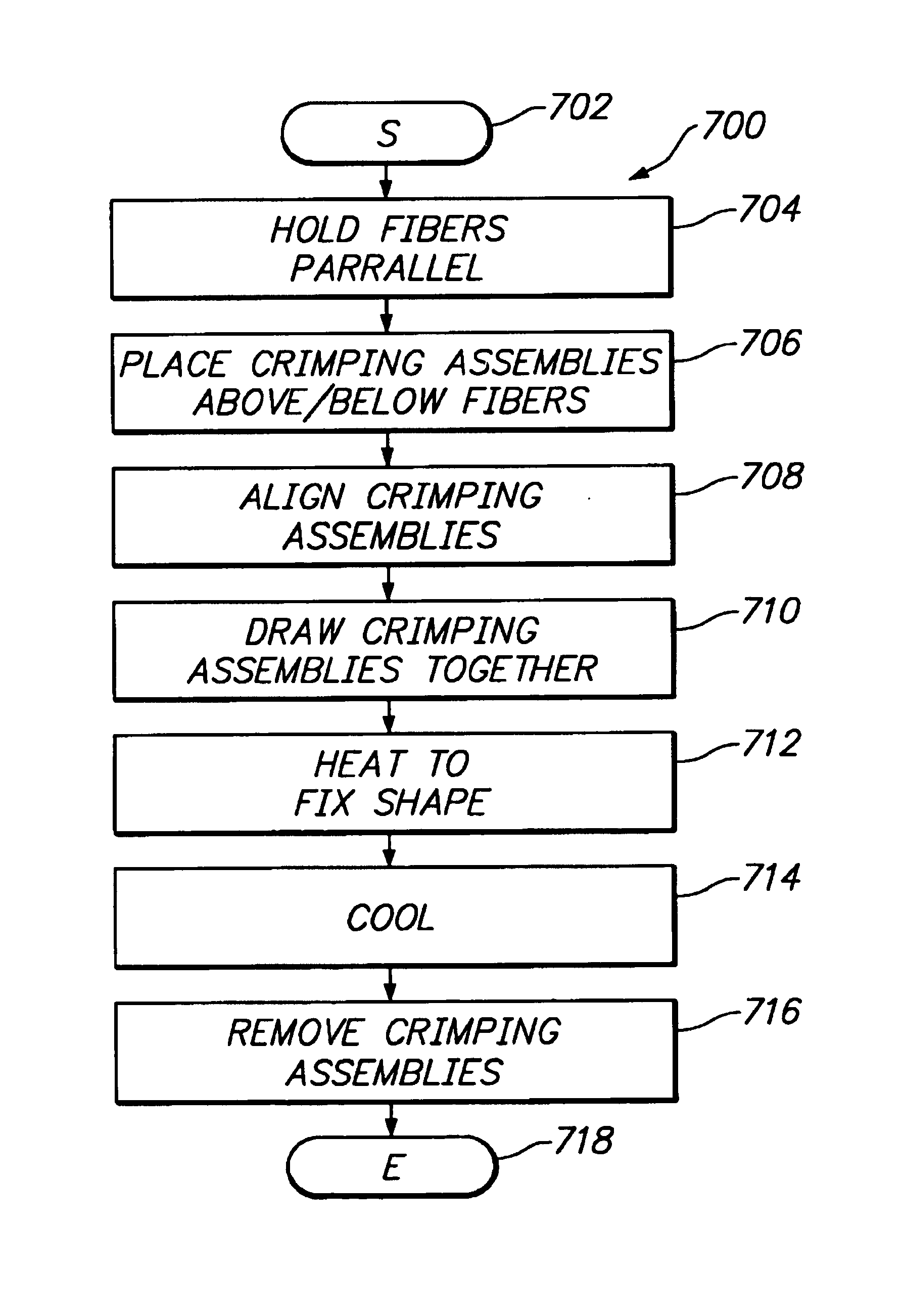
[0012]To achieve wider fiber distribution, the present invention introduces techniques to selectively shape hollow fibers. Shaping may be performed to introduce divergence (“splay”) among the fibers, or alternatively to introduce a selected longitudinal oscillation into the fibers. In one shaping technique, the fibers are held in parallel while opposing assemblies of parallel crimping bars are drawn together on opposite sides of the parallel fibers. When bars of the opposing assemblies draw sufficiently close, they sandwich the fibers in between them, causing each fiber to assume a shape that oscillates as it repeatedly goes over and then under successive bars. The crimping bars are aligned at oblique angles to the fibers; thus, the peaks and troughs of each fiber are offset from every other fiber. While in this position, the fibers are heated and then cooled to permanently establish their shapes. To facilitate heating, the bars can be designed to contain a circulating heating fluid. Or, shape irregularities can be introduced into the fibers during fabrication when the fibers are malleable by directing air or objects against the fibers.
[0014]The invention affords its users with a number of distinct advantages. For example, in comparison with conventional multi-fiber catheters, catheters of this invention exchange heat or materials with improved efficiency because the fibers are more thoroughly separated from each other. Either by splaying fibers away from each other, or by creating fibers that oscillate with a staged phase delay, the invention encourages fiber spreading. This helps avoid the creation of a common boundary layer among several fibers, since the fibers are more likely to be spread apart. The invention also provides a number of other advantages and benefits, which should be apparent from the following description of the invention.

Problems solved by technology

Otherwise, without any narrowing of the retainers, the fibers may be excessively stretched or sheared while the crimping assemblies force the fibers to assume a longer, curving path.

Method used


Image

  • Method of selectively shaping hollow fibers of heat exchange catheter
  • Method of selectively shaping hollow fibers of heat exchange catheter
  • Method of selectively shaping hollow fibers of heat exchange catheter

Examples


Embodiment Construction

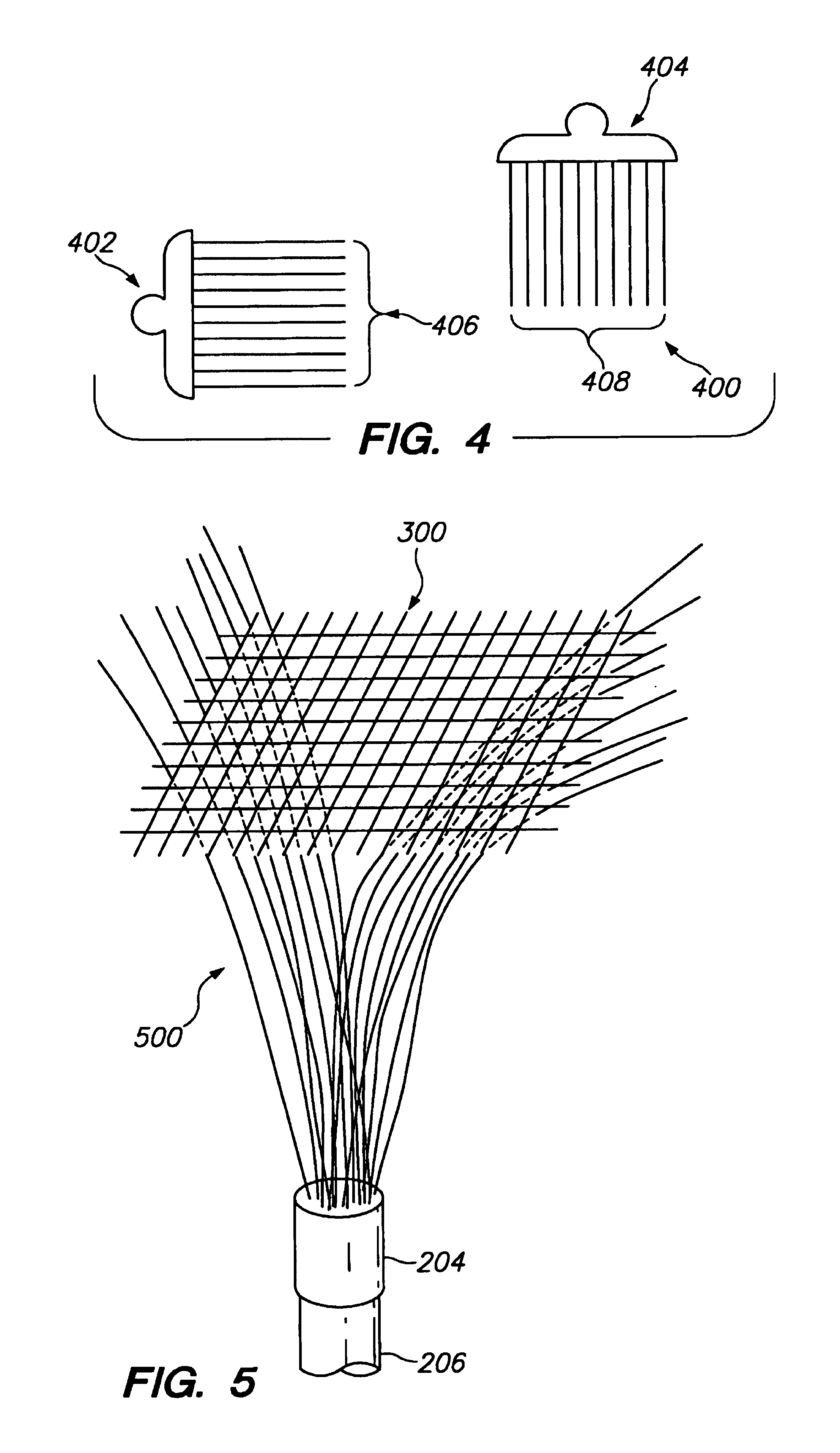
[0032]The nature, objectives, and advantages of the invention will become more apparent to those skilled in the art after considering the following detailed description in connection with the accompanying drawings. As mentioned above, the invention concerns techniques for selectively shaping hollow fibers designed to exchange heat or materials with body fluids / tissue. As examples, hollow fibers are discussed herein, even though the fiber shaping techniques of this invention are similarly applicable to solid fibers. These techniques may be applied to introduce divergence among fibers in a bundle as the fibers exit a common point of attachment, or alternatively to introduce a selected longitudinal oscillation into the fibers.

Fiber Splaying

INTRODUCTION

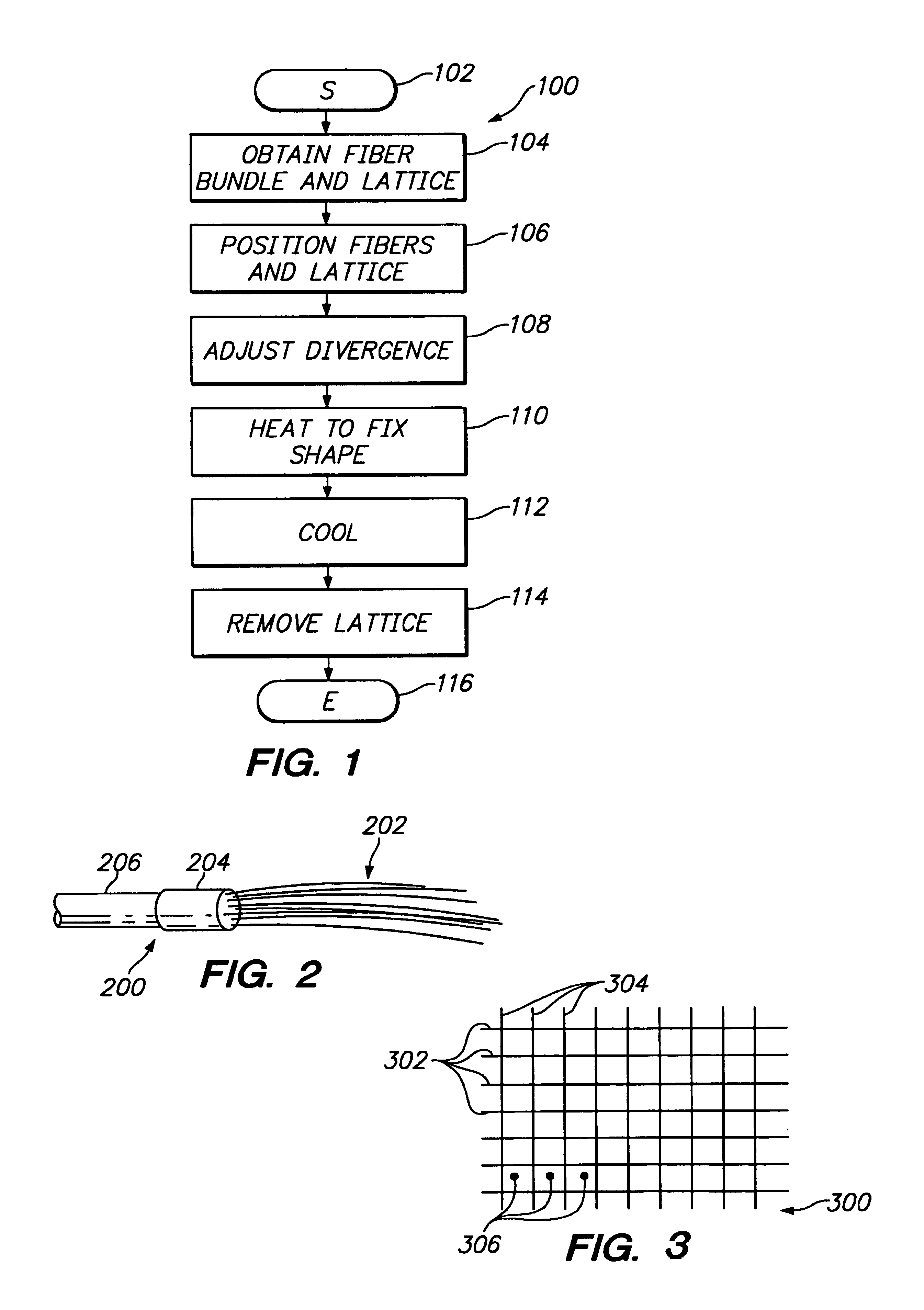
[0033]FIG. 1 shows a sequence 100 to illustrate one example of the method aspect of the present invention. For ease of explanation, but without any intended limitation, the example of FIG. 1 is described in the context of various hardware...


PUM

PropertyMeasurementUnit
angleaaaaaaaaaa
angleaaaaaaaaaa
angleaaaaaaaaaa

Abstract

A group of multiple hollow fibers may be shaped to introduce angular divergence among the fibers, or to introduce a selected longitudinal oscillation into the fibers. In one shaping technique, the fibers are held in parallel while upper and lower crimping assemblies of parallel crimping bars are drawn together on opposite sides of the parallel fibers. When bars of the opposing assemblies draw sufficiently close, they sandwich the fibers in between them, causing each fiber to assume a shape that oscillates as the fiber repeatedly goes over and then under successive bars. Since the crimping bars are aligned at oblique angles to the fibers, the peaks and troughs of successive fibers are offset. While in this position, the fibers are heated and then cooled to permanently retain their shapes. A different shaping technique utilizes a lattice of criss-crossing tines defining multiple apertures. In this technique, the lattice and fibers are positioned so that each fiber passes through one of the apertures. Then, the lattice and / or the fibers are slid apart or together until the lattice holds the fibers in a desired configuration, where the fibers have a prescribed outward divergence relative to each other. While in this position, the fibers are heated and then cooled to permanently retain this angular divergence. The heating can be effected using heating fluid or gas circulated in the bars.

Description

RELATED APPLICATIONS[0001]This application is a continuation-in-part of U.S. patent application Ser. No. 09 / 321,515 filed May 27, 1999, now U.S. Pat. No. 6,165,207.BACKGROUND OF THE INVENTION[0002]1. Field of the Invention[0003]The present invention relates to catheters that utilize a bundle of many small fibers to conduct heat or materials exchange with a target area of the human body. More particularly, the invention concerns a catheter manufacturing process that selectively shapes a group of multiple hollow fibers to introduce angular divergence among the fibers or to introduce a selected longitudinal oscillation into the fibers.[0004]2. Description of the Related Art[0005]In warm blooded creatures, temperature regulation is one of the most important functions of the body. Despite the known importance of properly maintaining body temperature, scientists have discovered certain beneficial effects of artificially inducing a hypothermic state. For instance, cooling the body can help...

Claims


Application Information

Patent Timeline
Patent Type & Authority Patents(United States)
IPC IPC(8): D01D5/22A61F7/00B29C33/02B29C53/02A61F7/12F28F21/06
CPCA61F7/12F28F21/062Y10T428/2976A61F2007/0054
Inventor BALDING, DAVID P.FOSTER, STEVEN C.
Owner ZOLL CIRCULATION
Learn More