Multihole patch for combustor liner of a gas turbine engine

Inactive Publication Date: 2006-08-08
GENERAL ELECTRIC CO
View PDF21 Cites 31 Cited by
  • Summary
  • Abstract
  • Description
  • Claims
  • Application Information

AI Technical Summary

Problems solved by technology

None of these patents, however, disclose the use of discrete patches of multiholes being provided to augment the cooling film provided by cooling slots on nuggeted liners.
This limits the flexibility of the pattern to address the specific thermal gradients experienced by the liner.
While this combustor is able to minimize emissions, it has been found that an extraordinary amount of hot gases impinge on the inner liner thereof.
Such hot gas impingement has been found to produce early oxidation of the forward liner panels, which results in reduced life and combustor burn through in severe cases.
This method has been effective in those cases where there is sufficient space to drill the required number / size of the holes for decreasing the panel temperature to an acceptable level, but the required space is not available in every instance.

Method used


Image

  • Multihole patch for combustor liner of a gas turbine engine
  • Multihole patch for combustor liner of a gas turbine engine
  • Multihole patch for combustor liner of a gas turbine engine

Examples


Embodiment Construction

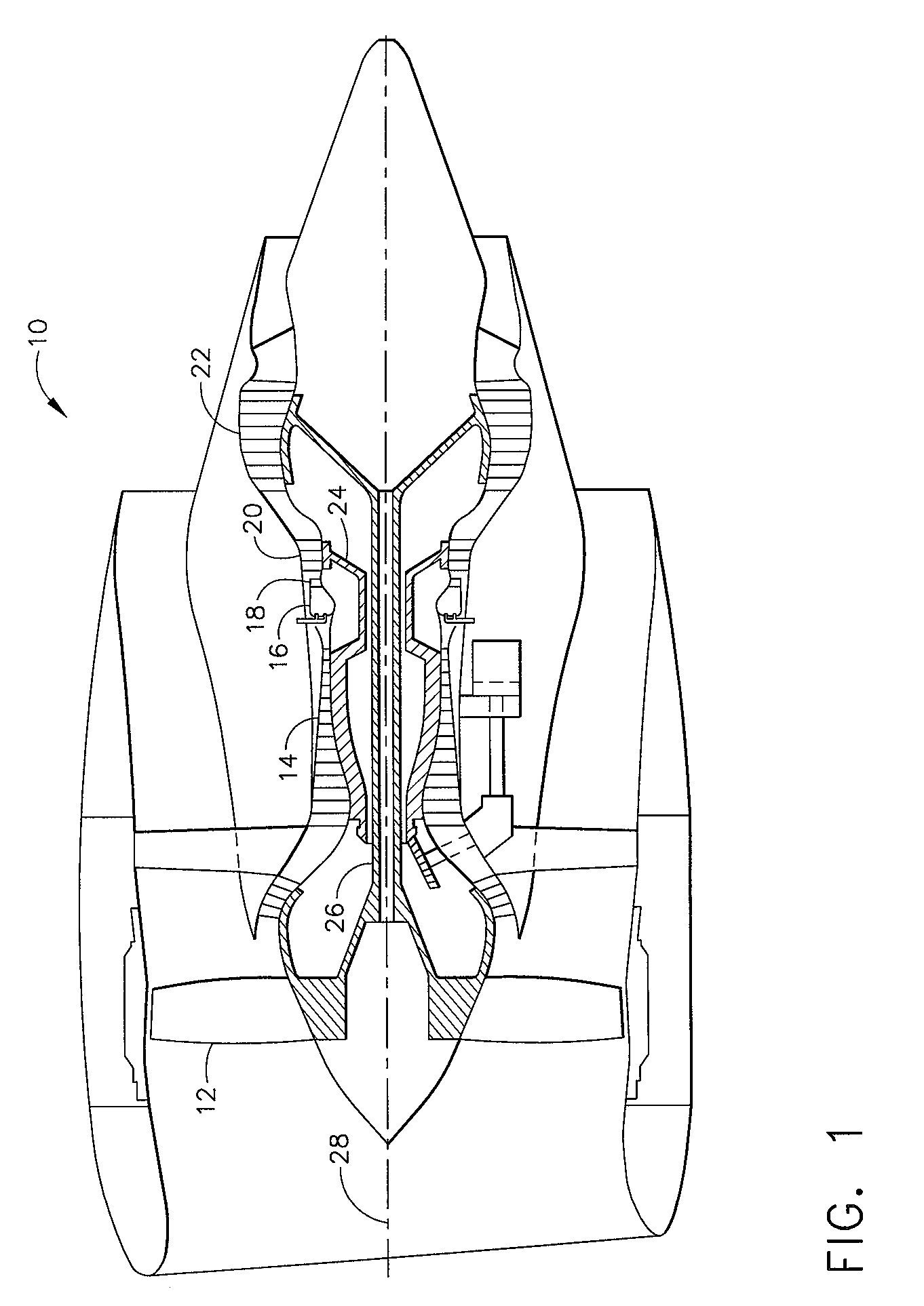
[0014]Referring now to the drawings in detail, wherein identical numerals indicate the same elements throughout the figures, FIG. 1 depicts an exemplary gas turbine engine 10 having in serial flow communication a fan 12, a high pressure compressor 14, and a combustor 16. Combustor 16 conventionally generates combustion gases that are discharged therefrom through a high pressure turbine nozzle assembly 18, from which the combustion gases are channeled to a conventional high pressure turbine 20 and, in turn, to a conventional low pressure turbine 22. High pressure turbine 20 drives high pressure compressor 14 through a suitable shaft 24, while low pressure turbine 22 drives fan 12 through another suitable shaft 26, all disposed coaxially about a longitudinal or axial centerline axis 28.

[0015]As seen in FIG. 2, combustor 16 further includes a combustion chamber 30 defined by an outer liner 32, an inner liner 34, and a dome 36 located at an upstream end thereof. It will be seen that a f...


PUM


Abstract

A liner for a combustor of a gas turbine engine, including a shell having a first end adjacent to an upstream end of the combustor and a second end adjacent to a downstream end of the combustor, wherein at least one discrete region is subject to distress from impingement of hot gases, a plurality of cooling slots formed in the shell through which air flows for providing a cooling film along a hot side of the shell, and a group of cooling holes formed in the shell in the discrete region to augment the cooling film and provide convective bore cooling to the discrete region.

Description

BACKGROUND OF THE INVENTION[0001]The present invention relates generally to film cooled combustor liners for use in a gas turbine engine and, in particular, to such combustor liners including a multihole patch of cooling holes formed in regions thereof which experience an undesirable thermal gradient.[0002]Combustor liners are generally used in the combustion section of a gas turbine engine located between the compressor and turbine sections of the engine, although such liners may also be used in the exhaust sections of aircraft engines that employ augmenters. Combustors generally include an exterior casing and an interior combustor where fuel is burned to produce a hot gas at an intensely high temperature (e.g., 3000° F. or even higher). To prevent this intense heat from damaging the combustor case and the surrounding engine before it exits to a turbine, a heat shield or combustor liner is provided in the interior of the combustor.[0003]Various liner designs have been disclosed in ...

Claims


Application Information

Patent Timeline
IPC IPC(8): F02C1/00F02G3/00F02C7/18F23R3/06F23R3/50
CPCF23R3/06F23R3/50Y02T50/675F23R2900/03042Y02T50/60
Inventor MOERTLE, GEORGE ERICMILLS, BRUCE ERNESTHOLMES, JAMES PATRICKLIND, DAVID ALBINHARRIS, TARIZ KAY
Owner GENERAL ELECTRIC CO
Why Eureka
Try Eureka