Thermal and compressed air storage system

a technology of compressed air and storage system, which is applied in the direction of indirect heat exchangers, machines/engines, light and heating apparatus, etc., can solve the problems of harmful emissions, not providing the most cost-effective heating method, and high overall operating cost, so as to reduce pollution at the source, and increase efficiency

Inactive Publication Date: 2006-08-08
P10 IND INC
View PDF26 Cites 152 Cited by
  • Summary
  • Abstract
  • Description
  • Claims
  • Application Information

AI Technical Summary

Benefits of technology

[0008]These and other objects of the present invention are accomplished in accordance with the principles of the present invention by providing various TACAS systems that are capable of supplying electrical power with increased efficiency and reduced point source pollution. This reduction of point source pollution is particularly beneficial when the location of the TACAS system makes ventilation difficult, although it may be desirable to reduce the harmful emissions by eliminating the use of a fuel-combustion system in other circumstances as well.

Problems solved by technology

Such known CAS systems, however, suffer from various deficiencies such as wasted heat during the air compression process, which can result in higher overall operating costs, and a constant requirement for fuel to continuously heat the compressed air.
In particular, the fuel-combustion process used in prior CAS systems in order to heat the compressed air produces harmful emissions, and depending on the duty cycle of the heating process, may not provide the most cost effective method of heating.

Method used


Image

  • Thermal and compressed air storage system
  • Thermal and compressed air storage system
  • Thermal and compressed air storage system

Examples


Embodiment Construction

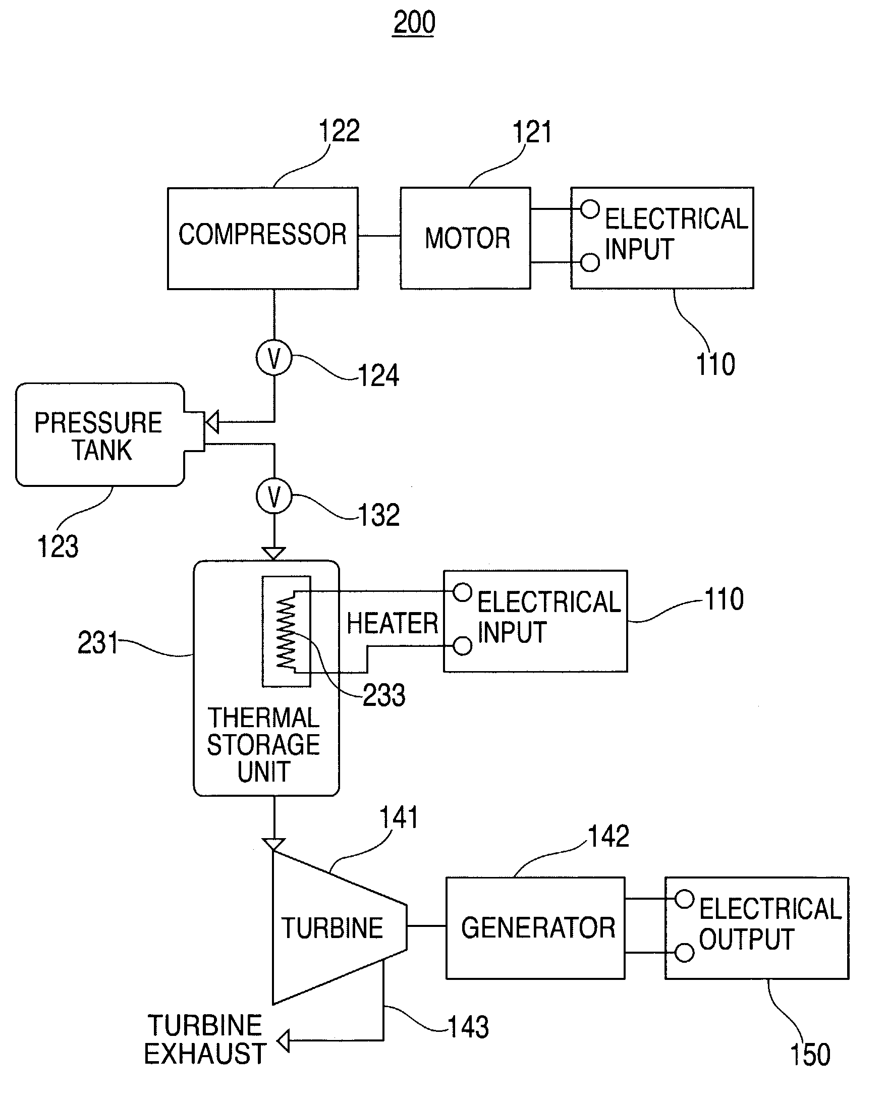
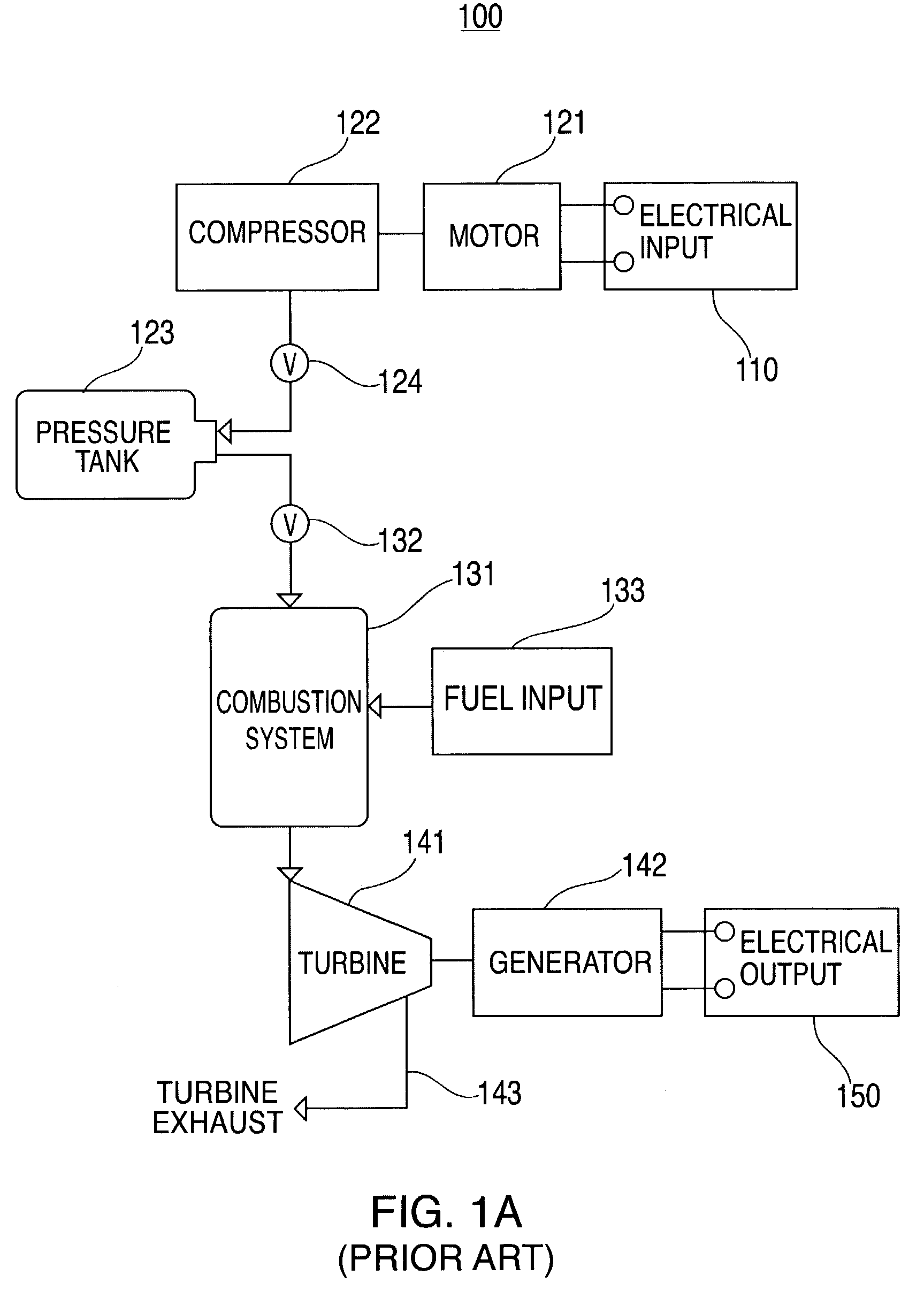
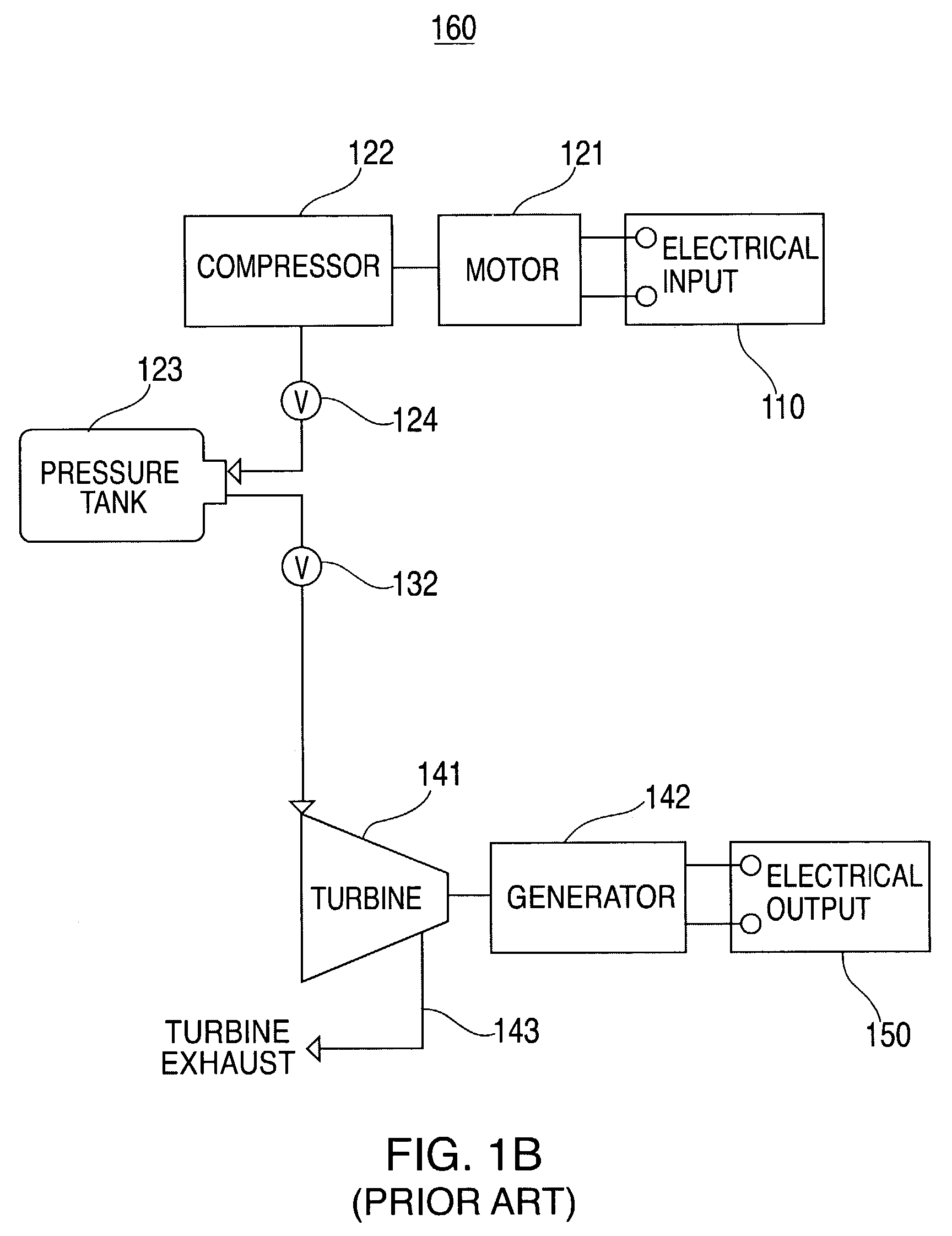
[0024]FIG. 1A shows a conventional CAS system 100 for providing output power.

[0025]CAS system 100 includes an electrical input 110 that provides input power to motor 121, which may be any conventional type of motor (e.g., a rotary electric machine). Electrical input 110 may be utility power or, for example, a battery or other short term power supply. Motor 121 is coupled to compressor 122 so that when motor 121 is receiving power from electrical input 110, it drives compressor 122. Compressor 122 supplies compressed air through a valve 124 into pressure tank 123. Compressor 122 may be any type of compressor which compacts or compresses air (e.g., atmospheric air) to occupy a smaller space inside of pressure tank 123.

[0026]As shown in FIG. 1A, pressure tank 123 is connected to compressor 122 through valve 124. It should be understood, however, that pressure tank 123 may be replaced with any other suitable type of air reservoir capable of storing compressed air. For example, an underg...


PUM


Abstract

Combined thermal and compressed air storage systems are provided that utilize an exhaustless heater, such as a thermal storage unit, to provide power with enhanced efficiency. Compressed air is heated by the thermal storage unit prior to entering a turbine, which powers an electrical generator. In various embodiments, ambient air temperature, turbine exhaust or other types of waste heat are used to preheat the compressed air prior to the compressed air entering the thermal storage unit, thereby further increasing system efficiency.

Description

BACKGROUND OF THE INVENTION[0001]This invention relates to compressed air storage (CAS) systems. More particularly, this invention relates to CAS systems that provide increased system efficiency, lower emissions and reduced system cost compared to known CAS systems.[0002]CAS systems are well known. Such systems, often used to provide an available source of electrical power, often use compressed air stored in an air tank that is heated and routed to drive a turbine which powers an electrical generator.[0003]Alternatively, rather than heating compressed air from the air tank prior to it being supplied to a turbine, some CAS systems utilize larger pressure tanks and forego the heating process.[0004]One known configuration of a CAS system includes a motor that, when powered by utility power, compresses air into a tank. When electrical power is desired, compressed air from the pressure tank is routed through a fuel-combustion system that heats the compressed air before it enters the turb...

Claims


Application Information

Patent Timeline
Patent Type & Authority Patents(United States)
IPC IPC(8): F01K25/02F02C1/05F02C6/16F02C7/08
CPCF02C1/05F02C6/16F28D20/00F02C7/08Y02E60/15Y02E60/16Y02E60/14
Inventor PINKERTON, JOSEPH F.
Owner P10 IND INC
Why Eureka
Try Eureka