Inertial latching mechanism for disk drive actuator

Inactive Publication Date: 2006-08-01
WESTERN DIGITAL TECH INC
View PDF9 Cites 1 Cited by
  • Summary
  • Abstract
  • Description
  • Claims
  • Application Information

AI Technical Summary

Benefits of technology

[0015]The present invention has been made to solve those technical problems and it is therefore an object of the present invention to prevent the deterioration of the reading and writing performance due to the interference between the latching mechanism and the moving member of the actuator while the head slider is in an operational state.
[0018]According to a first aspect of the present invention, a disk drive comprises: a disk-shaped storage medium supported for rotation; a moving member supporting a read / write head for reading recorded data from the disk-shaped storage medium and writing data to the disk-shaped storage medium, and capable of moving the head between a read / write position where the head is able to read data from and write data to the disk-shaped storage medium and a home position where the head is separated from the disk-shaped storage medium; and a latching mechanism capable of securely holding the moving member in place when the head is located at the home position and of remaining separate from the moving member when the head is located at the read / write position.
[0023]In the disk drive, the latching mechanism may be an inertial latching mechanism that operates in response to an external shock. The latching mechanism may have a latching arm that moves in a predetermined allowable moving range in response to an external shock, and the latching arm may be capable of latching the lever in the allowable moving range when the head slider is located at the home position, and of remaining separate from the lever when the head slider is located at the read / write position. The lever may be formed in a shape such that the lever is outside an allowable moving range for the latching mechanism when the read / write head is located at the read / write position. The lever may have a recessed part for avoiding interference between the lever and the latching mechanism. The disk drive may further comprise a ramp for holding the head slider at the home position; wherein the latching mechanism latches the moving member in a sate where the head slider is held by the ramp.

Problems solved by technology

Consequently, the actuator 10 is dislocated, the magnetic head 13 is unable to operate normally for a data reading or writing operation, and thereby the performance of the hard disk drive 1 is deteriorated.

Method used


Image

  • Inertial latching mechanism for disk drive actuator
  • Inertial latching mechanism for disk drive actuator
  • Inertial latching mechanism for disk drive actuator

Examples


Embodiment Construction

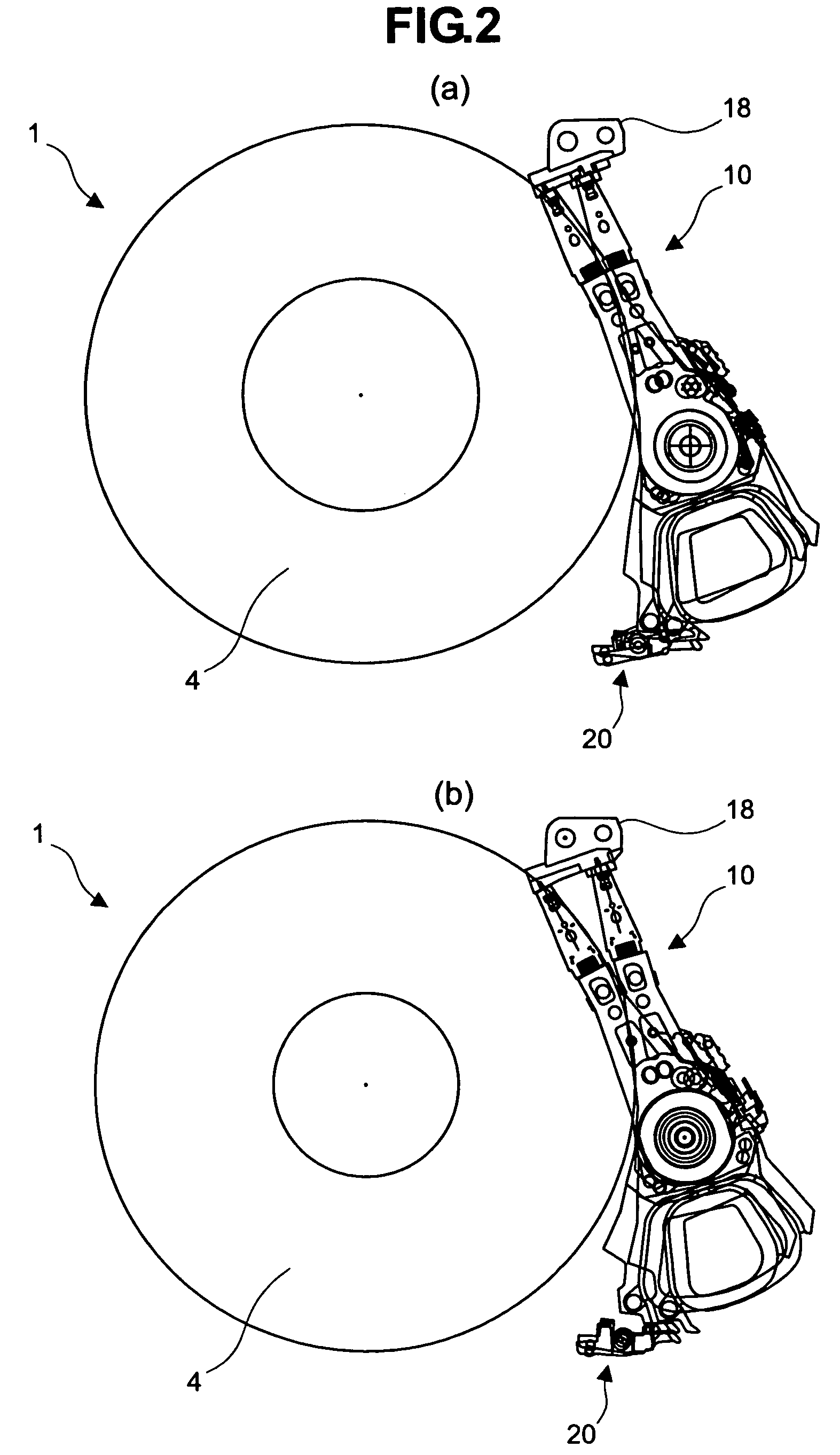
[0036]Embodiments of the present invention will be described with reference to the accompanying drawings. Hard disk drives embodying the present invention are the same in basic construction as the conventional hard disk drive shown in FIG. 7 and hence the description of the basic construction of the hard disk drives embodying the present invention will be omitted. FIG. 1 is a top view of a magnetic disk 4 and an actuator 10 (moving member, arm) included in a hard disk drive in a preferred embodiment according to the present invention. The actuator 10 is substantially the same in basic construction as the conventional actuator 10 shown in FIG. 8 and hence the parts thereof corresponding to those shown in FIG. 8 are denoted by the same reference characters and the description thereof will be omitted.

[0037]The actuator 10 included in the hard disk drive 1 in this embodiment is movable in a wide allowable moving range. More concretely, a home position to which a head slider 14 is retrac...


PUM


Abstract

The invention prevents the deterioration of the read / write performance of a hard disk drive due to the interference between an inertial latching mechanism and an actuator when a head slider holding a magnetic head is located at a read / write position. A latching arm 22 provided with a projection 23 and included in an inertial latching mechanism 20, and a part 161 of a coil holding arm 16a included in an actuator are formed in shapes such that the latching arm 22 provided with the projection 23 does not interfere with the coil holding arm 16a having the part 161 when a head slider mounted on the actuator is located at a read / write position on a magnetic disk.

Description

RELATED PATENT APPLICATION[0001]This application claims priority to Japanese Patent Application No. JP2002-348625 (Hitachi Global Storage Technologies Docket No. JP920020203US1), filed on Nov. 29, 2002, and entitled “Disk Drive.”BACKGROUND OF THE INVENTION[0002]1. Technical Field[0003]The present invention relates to a disk drive and, more particularly, to a disk drive provided with a latching mechanism for latching an actuator.[0004]2. Description of the Related Art[0005]A recent hard disk drive employs a head slider moving mechanism for moving a head slider supporting a magnetic head to prevent the head slider from sticking to the surface of a magnetic disk and to improve the reliability thereof in withstanding shocks applied thereto. The head slider moving mechanism holds an actuator on a part called a ramp disposed near the circumference of the magnetic disk to keep the head slider apart from the surface of the magnetic disk while the hard disk drive is not in operation.[0006]FI...

Claims


Application Information

Patent Timeline
IPC IPC(8): G11B5/54G11B21/12G11B21/22
CPCG11B21/22G11B5/54
Inventor KANADA, NAOAKITAKAHASHI, KOHJIYOSHIDA, KAZUYOSHIYOSHIDA, KEIICHIROH
Owner WESTERN DIGITAL TECH INC
Why Eureka
Try Eureka