Method for determining the paper quality for halftone printing

a paper quality and autotypical technology, applied in the direction of material analysis, optically investigating flaws/contamination, instruments, etc., to achieve the effect of accurate and sensitive method, significant improvement of paper quality, and improved detection of paper faults

Inactive Publication Date: 2006-08-01
IGT TESTING SYST
View PDF6 Cites 0 Cited by
  • Summary
  • Abstract
  • Description
  • Claims
  • Application Information

AI Technical Summary

Benefits of technology

[0012]The pattern on this optically transparent surface element is uniform. If the paper quality is different over the region of this surface element, differences in the lightness or, in the case of colored dots, possibly also in the color will be detected by eye immediately. In this way, faults in the paper will be detected significantly better than if an image is printed on it which intrinsically already has different lightness graduations and is influenced by the dot transfer of the printing process.
[0013]The invention therefore provides, in a surprisingly simple way, a very accurate and sensitive method of checking the paper quality before printing. The method can be applied not only in the case of the coated paper but also in the case of machine-finished paper.

Problems solved by technology

In addition, this theoretically proposed method is not used to determine the quality of paper, in particular quality fluctuations, but for checking mathematical models of the aforementioned apparent enlargement of the dots.
However, according to the statements of the author of the aforementioned dissertation, this method, with which the dot gain is again to be examined, suffers from the fact that surface reflections occur which are not present in a normal print, which falsifies the result.
In addition, this method was obviously used only for the theoretical examination of the dot gain mechanism, not for determining the paper quality.

Method used


Image

  • Method for determining the paper quality for halftone printing
  • Method for determining the paper quality for halftone printing
  • Method for determining the paper quality for halftone printing

Examples


Embodiment Construction

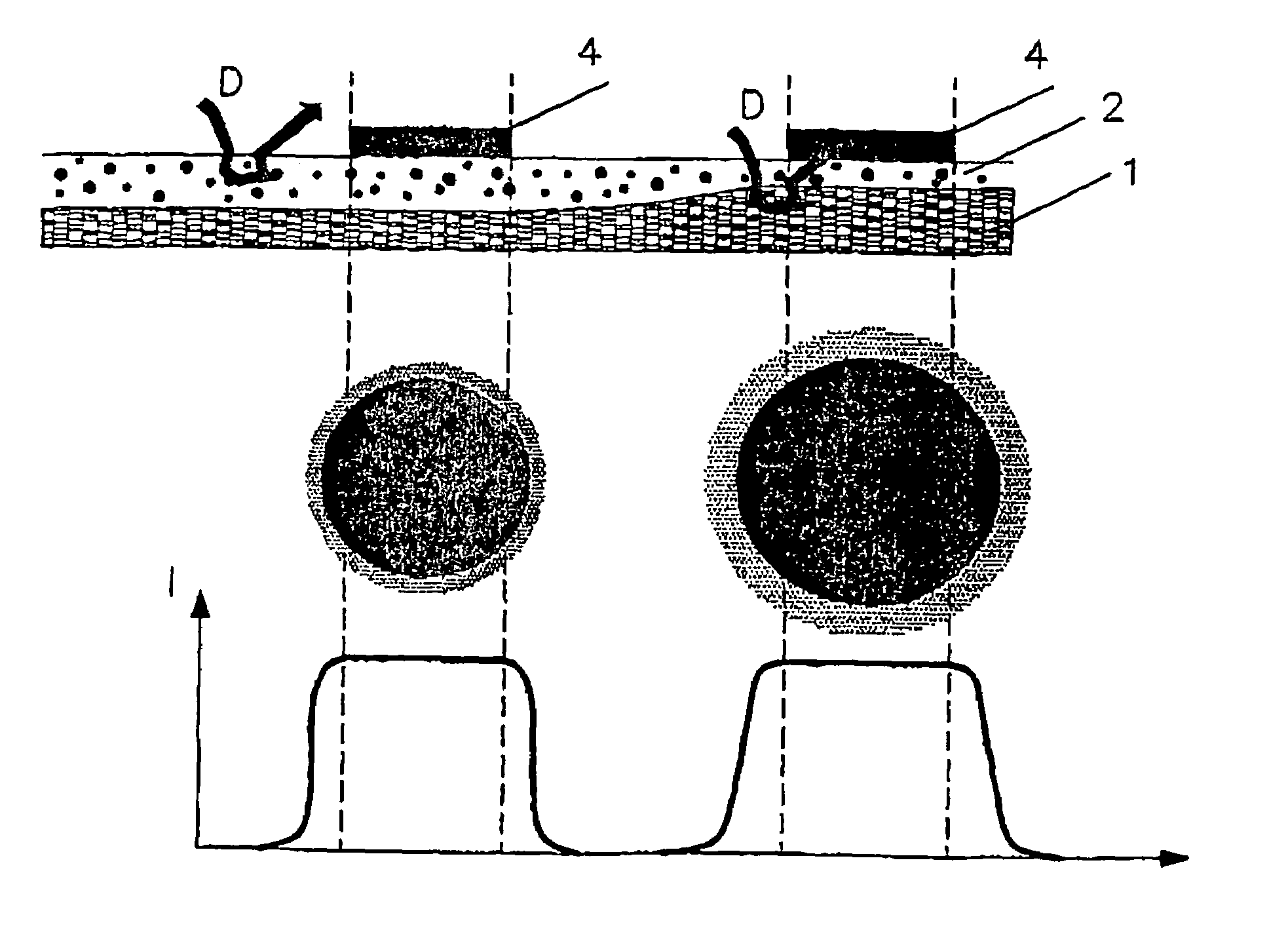
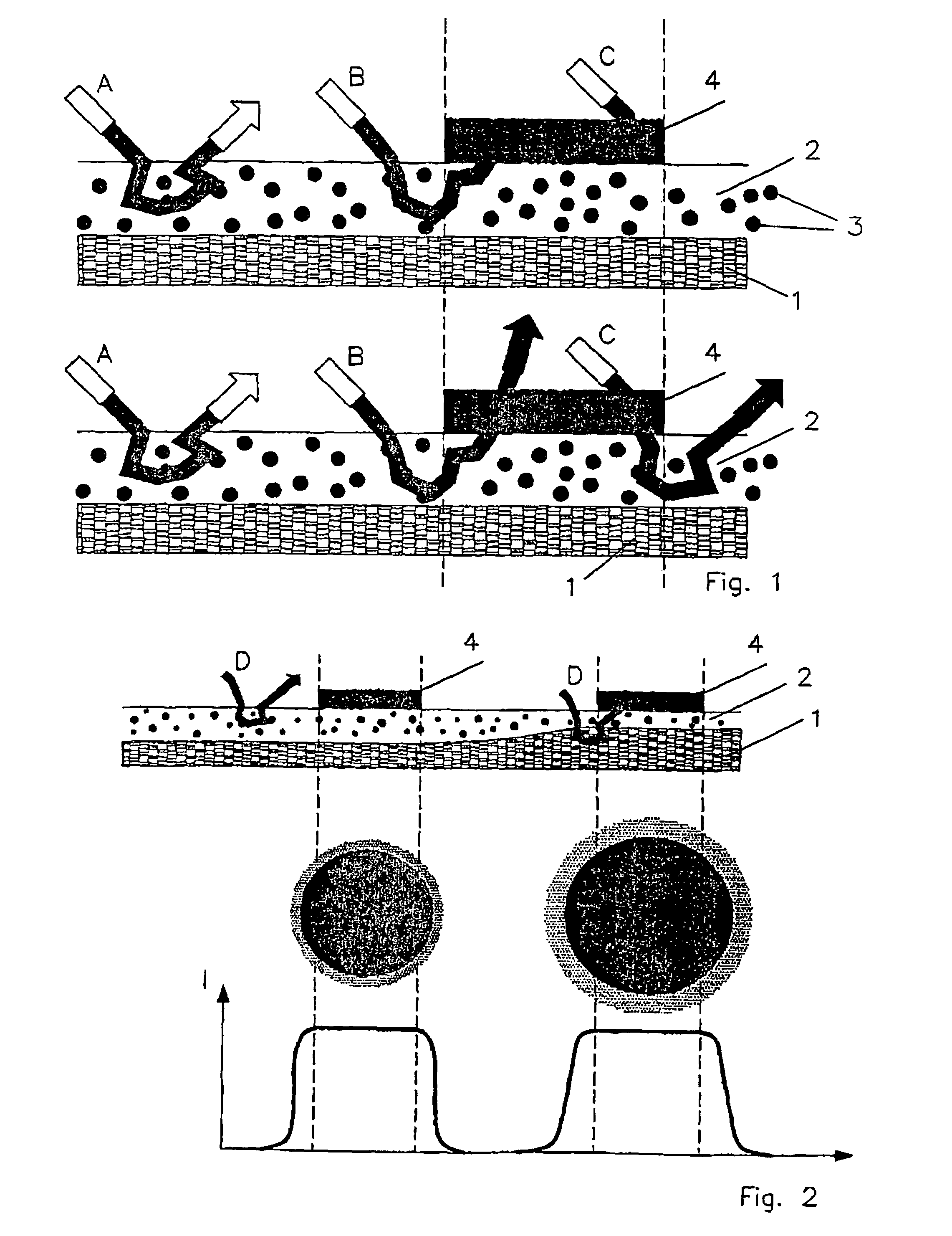
[0030]As FIG. 1 shows, a partly translucent coating 2 which, for example, has pigments 3 is applied to a paper substrate 1 composed of fibers. Light beams A, B and C are scattered differently. In this case, the upper part of FIG. 1 shows a black opaquely printed dot 4, while in the lower part this printed dot 4 is partly transparent to light, like cyan inks, for example. The light beam A is scattered out of the coating 2 in both cases and therefore contributes to the lightness of the image at this point. In the upper illustration with a black printed dot, the light beam B is scattered under this printed dot 4 and therefore cannot leave the coating 2 again. A somewhat blurred, dark region will therefore occur around the printed dot 4, that is to say the dot 4 will appear to be larger than it actually is. It is thereby not only light beams C which fall directly onto the printed dot 4 which are extinguished but also light beams which enter the coating 2 close to the dot 4.

[0031]In the ...


PUM

PropertyMeasurementUnit
transparentaaaaaaaaaa
pressureaaaaaaaaaa
areaaaaaaaaaaa

Abstract

The invention relates to a method for determining the paper quality for halftone printing, according to which a finely distributed pattern of geometric figures is applied to the paper, said paper is then illuminated and the light that is reflected and scattered by the paper is observed. The method is characterized in that the pattern is applied to an optical transparent planar element, the side of said element bearing the pattern is brought into contact with the surface of the paper and the paper is pressed against the planar element.

Description

BACKGROUND OF THE INVENTION[0001]The invention relates to a method of determining the paper quality for autotypical halftone printing, in which a finely distributed pattern of geometric figures is applied to the paper, the paper is illuminated and the light reflected and scattered by the paper is observed.[0002]During printing, the problem occurs that gray tones can be reproduced only poorly. In order nevertheless to be able to produce prints of good quality with graduated lightness tones, use is therefore made to a widespread extent of the technique of autotypical halftone printing, as it is known. In this case, the image is no longer determined by continuous lightness transition. Instead, the image is built up from a finely distributed pattern of geometric figures, which are normally dots. In a widespread printing technique, these dots are arranged regularly in a grid. Depending on the lightness value at a specific point of the image to be printed, these dots are made larger or sm...

Claims


Application Information

Patent Timeline
Patent Type & Authority Patents(United States)
IPC IPC(8): G01N21/47G01B11/30G01N21/55G01N21/86G01N1/00G01N21/88G01N33/34
CPCG01N33/34G01N21/55
Inventor CARL, GERD
Owner IGT TESTING SYST
Why Eureka
Try Eureka