
Signal transmission device

a signal transmission and signal technology, applied in the field of signal transmission devices, can solve the problems of inability to use one and the same joystick, game pad or psx controller, and inability to use one and the same control device for the game console set forth above, and achieve the effect of simple and cost-effective connection

Inactive Publication Date: 2006-08-01
ZILLIG FREYA +1
View PDF5 Cites 36 Cited by
  • Summary
  • Abstract
  • Description
  • Claims
  • Application Information

AI Technical Summary

Benefits of technology

"The invention is a device that allows a player to control a video game or PC through an exercise machine. The device is compatible with various video game consoles and PCs, making it easy to connect and control. It uses electronic circuitry to convert signals from the exercise machine to the game console or PC, allowing for seamless integration. The device is cost-effective and can be easily installed in existing exercise machines or fitness studios. It offers an interactive and engaging experience for the player, increasing motivation and enjoyment of the game."

Problems solved by technology

A further disadvantage lies in the fact that PC or video game consoles are not compatible with each other.
This means that is not possible to use one and the same joystick, game pad or PSX controller in order to connect to various video game consoles or to the PC.
This means that, even if a plug-in adapter is inserted between the game console, on one hand, and the control device, on the other hand, the use of one and the same control device for the game consoles set forth above is not possible.
Moreover, both the electronic circuitry and the connections of video game consoles are different from those of the PCs commonly to be found in trade—for example, IBM-compatible PCs—meaning that there can be no compatibility between these devices as well.

Method used


Image

  • Signal transmission device
  • Signal transmission device
  • Signal transmission device

Examples


Embodiment Construction

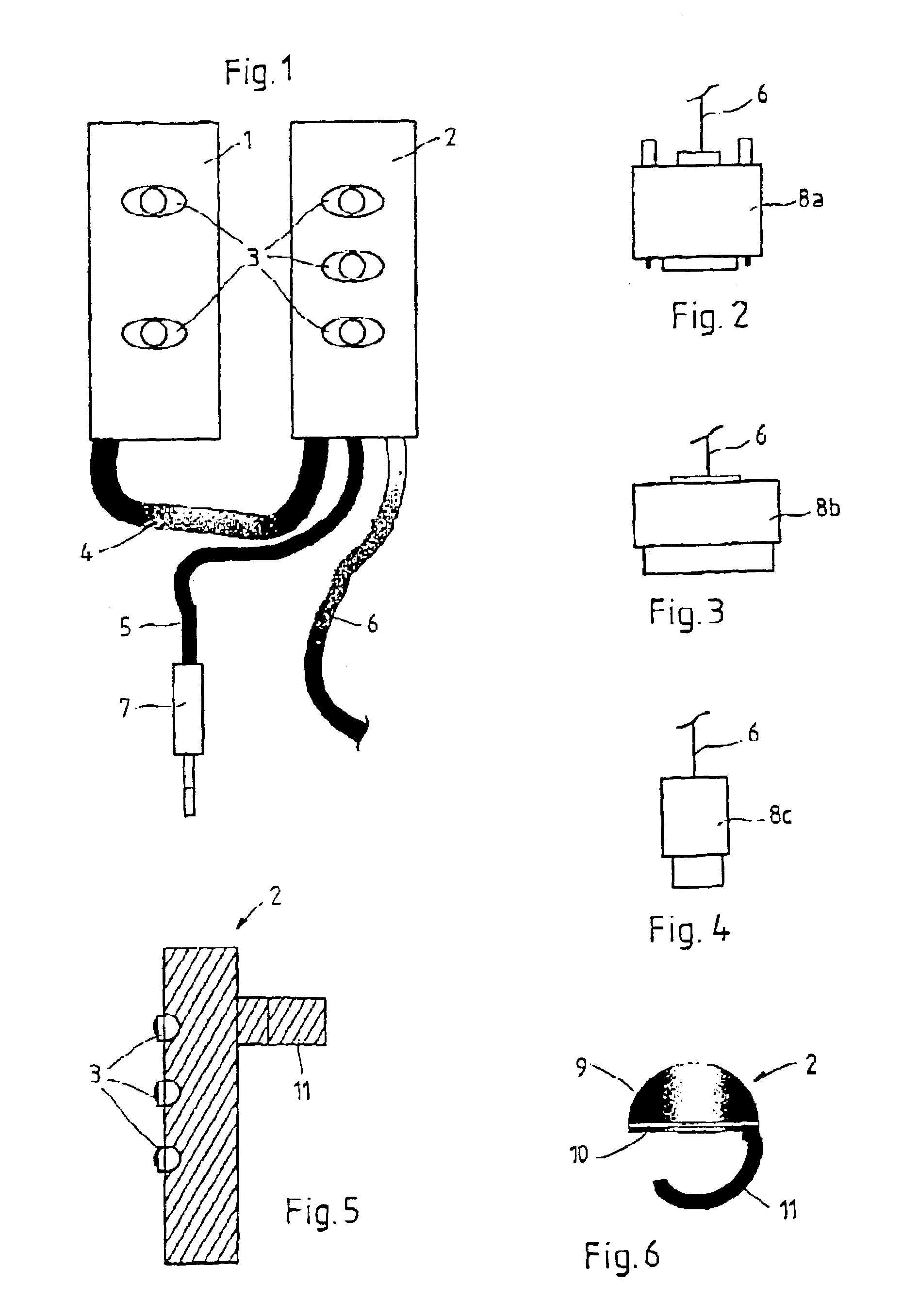
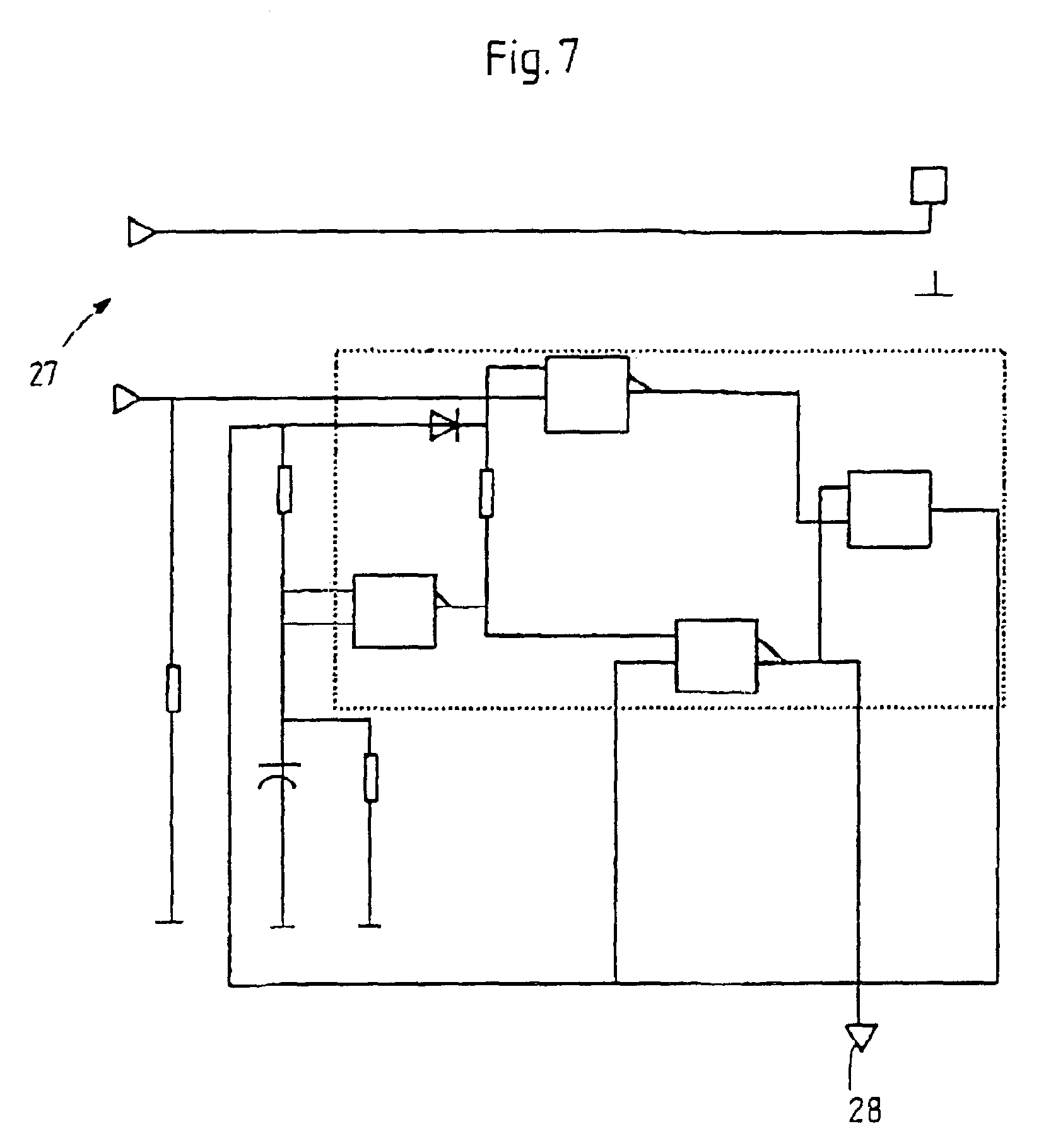
[0045]The device according to the invention enables the coupling, for the purpose of communication, of exercise machines, on one hand, and PCs and / or video game consoles, on the other hand. The particular attraction of this coupling for the purpose of communication lies in the fact that the physical operating conditions of the person using the exercise machine, which are recorded by means of the signal transmitter connected to the exercise machine, may be used to at least partially control a video game which can be run on a PC or a video game console. The electronic circuitry switched in between the exercise machine and the PC or the video game console serves for the conversion of the signals generated by the signal transmitter in additional information which can be processed by the PC or the video game console.

[0046]Known video game consoles commonly to be found in trade include the Microsoft X-Box, the Nintendo Gamecube and the Sony Playstation. A factor common to all of these vid...


PUM


Abstract

The invention concerns a device for signal transmission from a signal transmitter which senses physical operating conditions to a separately installed signal receiver. In order to create a device by means of which the player of a PC or video game is given the possibility of interactive engagement in the course of the game, whereby said device is compatible, for purposes of control, with all of the video game consoles and PCs commonly to be found in trade, the invention proposes a device for signal transmission, wherein an electronic circuit is connected to the signal transmitter, on one hand, and to the signal receiver, on the other hand, and the signals generated by the signal transmitter may be converted, by means of said electronic circuit, to the structure required for the signal receiver, whereby the signal transmitter, in order to sense at least one physical operating condition, is connected to an exercise machine, and whereby a PC or a video game console is provided as the signal receiver.

Description

FIELD OF THE INVENTION[0001]The invention concerns a device for signal transmission from a signal transmitter which transmits physical operating conditions to a separately installed signal receiver.DESCRIPTION OF THE RELATED ART[0002]Devices of the type described above are known from prior state of technology—for example, from the control of PC or video games. Among the devices used in this type of application are joysticks, game pads, PSX controllers and similar devices, which are directly connected to the PC or the video console, and by means of which the player obtains the possibility of engaging or controlling the game. Movements of the joystick, game pad or PSX controller are converted into appropriate electrical signals and transmitted in the form of digital information to the PC or the video console. There, the incoming information signals are encoded and converted into corresponding movements of the figures represented in the video game.[0003]A factor common to all of the af...

Claims


Application Information

Patent Timeline
Patent Type & Authority Patents(United States)
IPC IPC(8): A63B21/00A63B22/00A63B24/00A63F13/02G06F3/00
CPCA63B24/0021A63F13/02G06F3/002A63B24/00A63B22/00Y10S482/90A63B71/0622A63B2024/0025A63B2024/0078A63B2071/0644A63B2220/833A63B2220/836A63B2225/50A63F2300/1025A63F2300/69A63F2300/535A63F2300/1037A63F13/65A63F13/98A63F13/573A63F2300/646A63F13/285A63F13/211A63F2300/105A63F13/23A63F13/90A63F13/28
Inventor ZILLIG, FREYAZILLIG, BODO
Owner ZILLIG FREYA
Learn More