Eureka AIR delivers breakthrough ideas for toughest innovation challenges, trusted by R&D personnel around the world.

Elevated airfield runway and taxiway edge-lights utilizing light emitting diodes

a technology of light-emitting diodes and airfield runways, applied in landing aids, instruments, roads, etc., can solve the problems of increased maintenance and replacement, incandescent lights with higher power requirements, and expensive and inefficient technology now considered

Inactive Publication Date: 2006-08-01
ADB SAFEGATE AMERICAS LLC
View PDF41 Cites 151 Cited by
  • Summary
  • Abstract
  • Description
  • Claims
  • Application Information

AI Technical Summary

Problems solved by technology

Airport runway edge lighting has been in existence for many years utilizing technology that is now considered costly and inefficient, requiring increased maintenance and replacement.
Conventional designs utilize incandescent lights that have higher power requirements, lower efficiency, and emit EMI (Electromagnetic Interference) and RFI (Radio Frequency Interference)—two undesirable components in an environment now more susceptible then ever to such interference signals.

Method used


Image

  • Elevated airfield runway and taxiway edge-lights utilizing light emitting diodes
  • Elevated airfield runway and taxiway edge-lights utilizing light emitting diodes
  • Elevated airfield runway and taxiway edge-lights utilizing light emitting diodes

Examples


Embodiment Construction

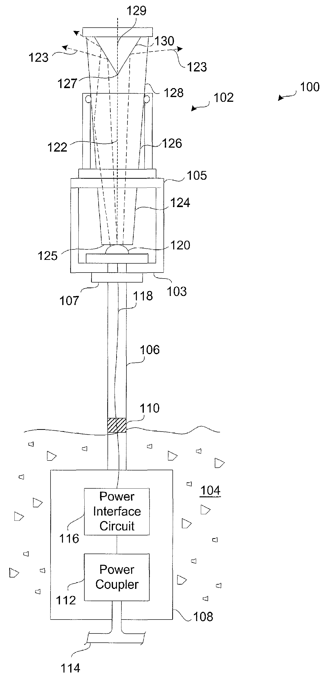
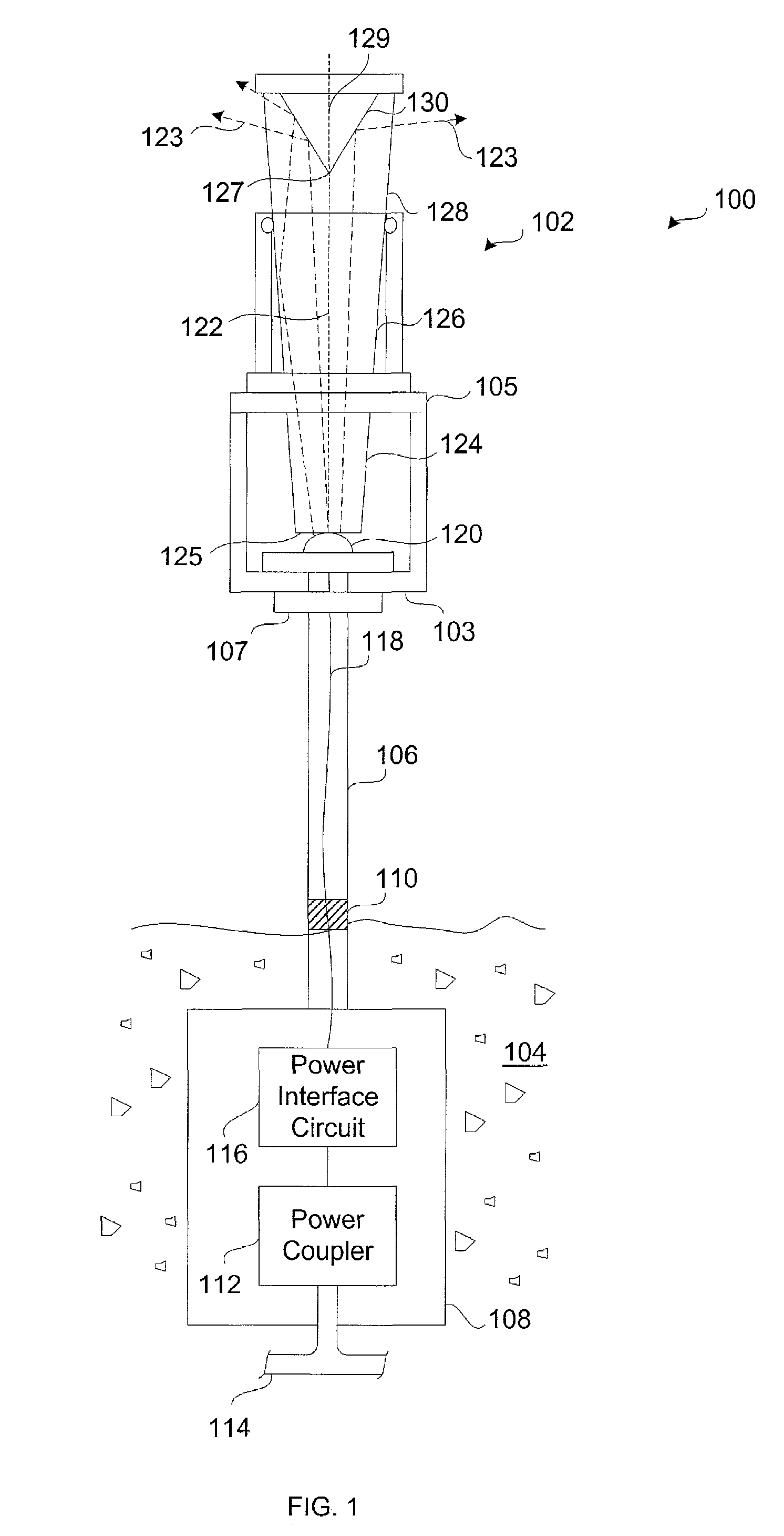
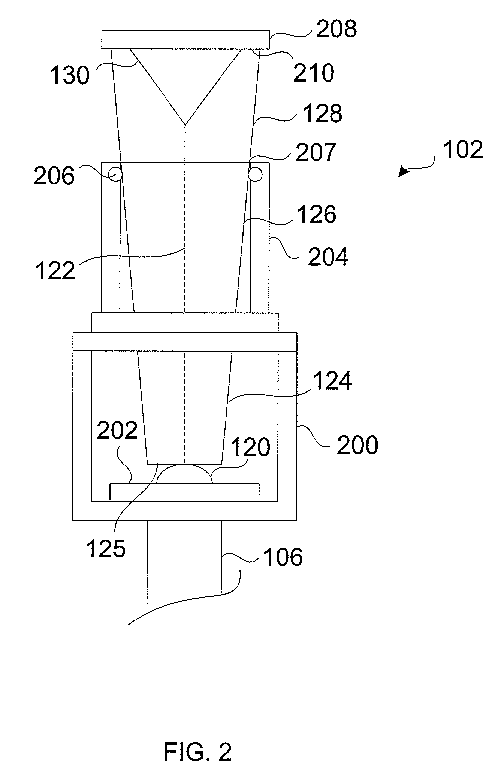
[0026]The present invention discloses a runway edge-lighting system that utilizes LEDs more efficiently by incorporating an optical coupler (or light pipe) in the form of a light-transmitting rod, wherein light is received into one end and dispersed from the other end by way of reflection from the surface of a conical concavity. One version of the rod is a tapered design, and is disclosed in U.S. Pat. No. 6,272,267 by Hansler et al., entitled “Optical Coupler and System for Distributing Light in a 360-Degree Pattern,” and that issued on Aug. 7, 2001, the entirety of which is hereby incorporated by reference.

[0027]The Federal Aviation Administration (FAA) stipulates that a runway lighting apparatus must meet certain photometric criteria, one criteria being that the light intensity projected from the lighting element must be at least 2.0 candela (a unit of luminous intensity) between 0 and 6 degrees from the horizontal axis (the horizontal axis being perpendicular to the longitudinal ...


PUM


Abstract

A runway and taxiway lighting system (of FIG. 1). The system (100) includes a housing (105) as part of a light assembly (102), which light assembly (102) includes a light source (120) for emitting light (123), and a light pipe (126). The light pipe (126) has a first end (124) in close association with the light source (120) for coupling the light (123) thereinto, and a second end (128) from which the light (123) is dispersed. The system (100) also includes a power source encased in a power box (108), and operatively connected to the light assembly (120) for providing power thereto.

Description

[0001]This application claims priority under 35 U.S.C. § 119(e) from U.S. Provisional Patent application Ser. No. 60 / 278,766 entitled “Elevated Airfield Runway and Taxiway Edge-Lights Using LEDs” and filed Mar. 26, 2001.[0002]This application is related to U.S. Pat. No. 6,272,267 by Hansler et al. entitled “Optical Coupler and System for Distributing Light in a 360-Degree Pattern” that issued on Aug. 7, 2001, and which claims priority from U.S. Provisional Patent application Ser. No. 60 / 072,168, filed on Jan. 6, 1998.BACKGROUND OF THE INVENTION[0003]1. Technical Field of the Invention[0004]This invention is related to airfield runway and taxiway lighting, and more particularly, a light system having an optical coupler for dispersing light therefrom whose light source is one or more Light Emitting Diodes (LEDs).[0005]2. Background of the Related Art[0006]Airport runway edge lighting has been in existence for many years utilizing technology that is now considered costly and inefficien...

Claims


Application Information

Patent Timeline
IPC IPC(8): E01F9/016F21S13/10G02B6/32B64F1/20E01F9/615F21S8/00F21V7/00F21V8/00G02B6/42
CPCB64F1/20F21V7/0008G02B6/0008G02B6/4298B64C2027/8236F21W2111/06F21V2200/20Y10S385/901F21V2200/10F21Y2101/02F21K9/61F21Y2115/10
Inventor HANSLER, RICHARD L.CAROME, EDWARD F.KUBULINS, VILNIS E.
Owner ADB SAFEGATE AMERICAS LLC
Why Eureka
Eureka Blog
Learn More