
Apparatus and method of using light sources of differing wavelengths in an unitized beam

a technology of light source and unit beam, which is applied in the direction of picture reproducers using projection devices, lighting and heating apparatus, lighting applications, etc., can solve the problems of difficulty in achieving suitable projected image brightness, and low optical performance of conventional projectors, so as to reduce the number of reflections encountered, reduce the loss of source intensity, and reduce the loss of intensity and resolution

Active Publication Date: 2006-08-01
SIGNIFY HLDG BV
View PDF83 Cites 105 Cited by
  • Summary
  • Abstract
  • Description
  • Claims
  • Application Information

AI Technical Summary

Benefits of technology

The solution provides a highly efficient, compact, and collimated light source with minimal intensity loss and dead space, enabling high contrast and collimated beams for applications like large format displays and digital projection systems.

Problems solved by technology

However, the optical performance of conventional projectors is often less than satisfactory.
For example, suitable projected image brightness is difficult to achieve, especially when using compact portable color projectors in a well-lighted room.
The optical path lengths are long and there are a number of reflections and filtration steps which must be performed with resulting loss in intensity and resolution.
Because LCD displays have significant light attenuation and triple path color light paths are heavy and bulky, portable multimedia projectors typically employ DMD displays in a single light path configuration.
Again the optical path ways are long, the optical system is necessarily physically large and the overall performance is still subject to intensity and collimation losses.

Method used


Image

  • Apparatus and method of using light sources of differing wavelengths in an unitized beam
  • Apparatus and method of using light sources of differing wavelengths in an unitized beam
  • Apparatus and method of using light sources of differing wavelengths in an unitized beam

Examples


Embodiment Construction

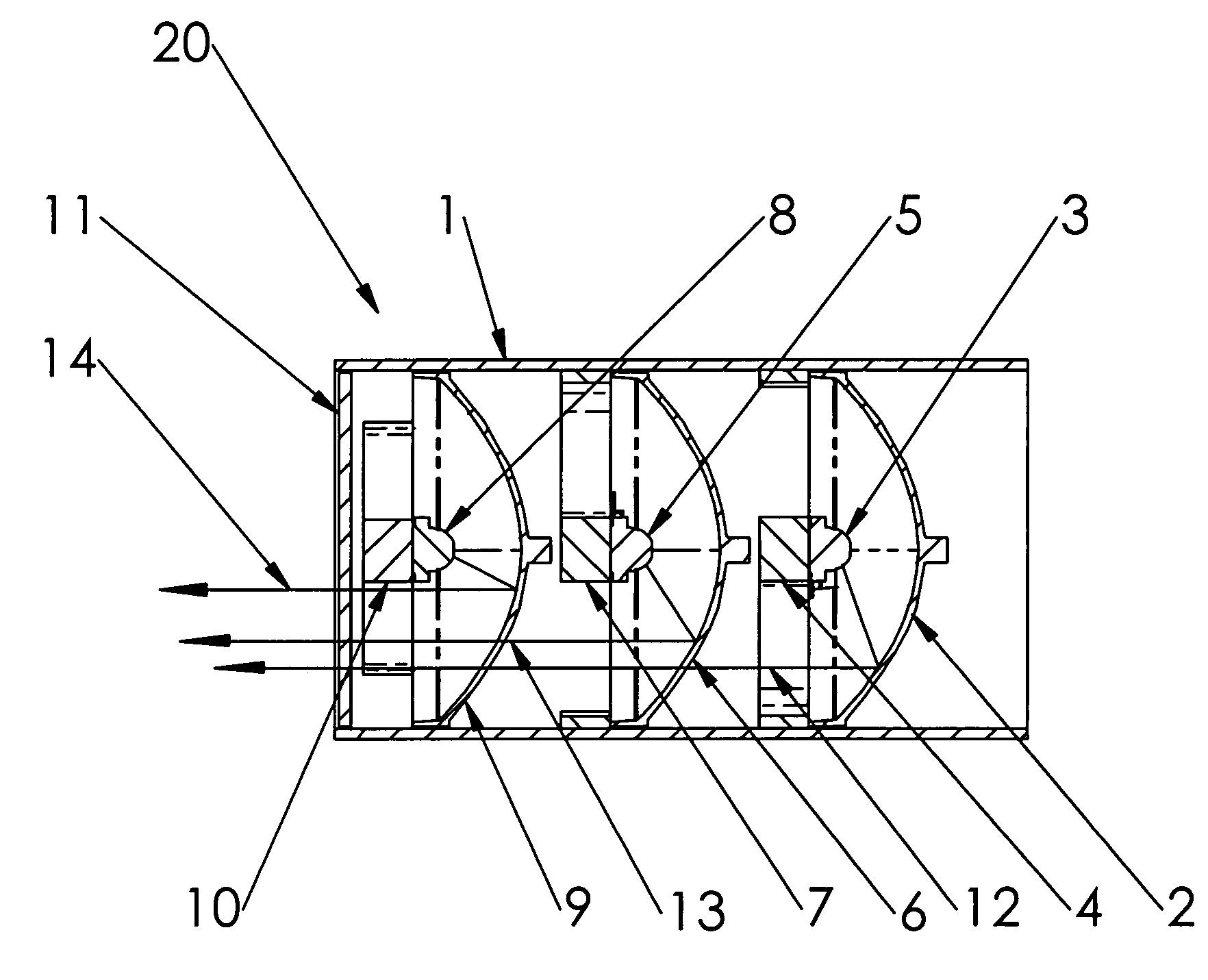
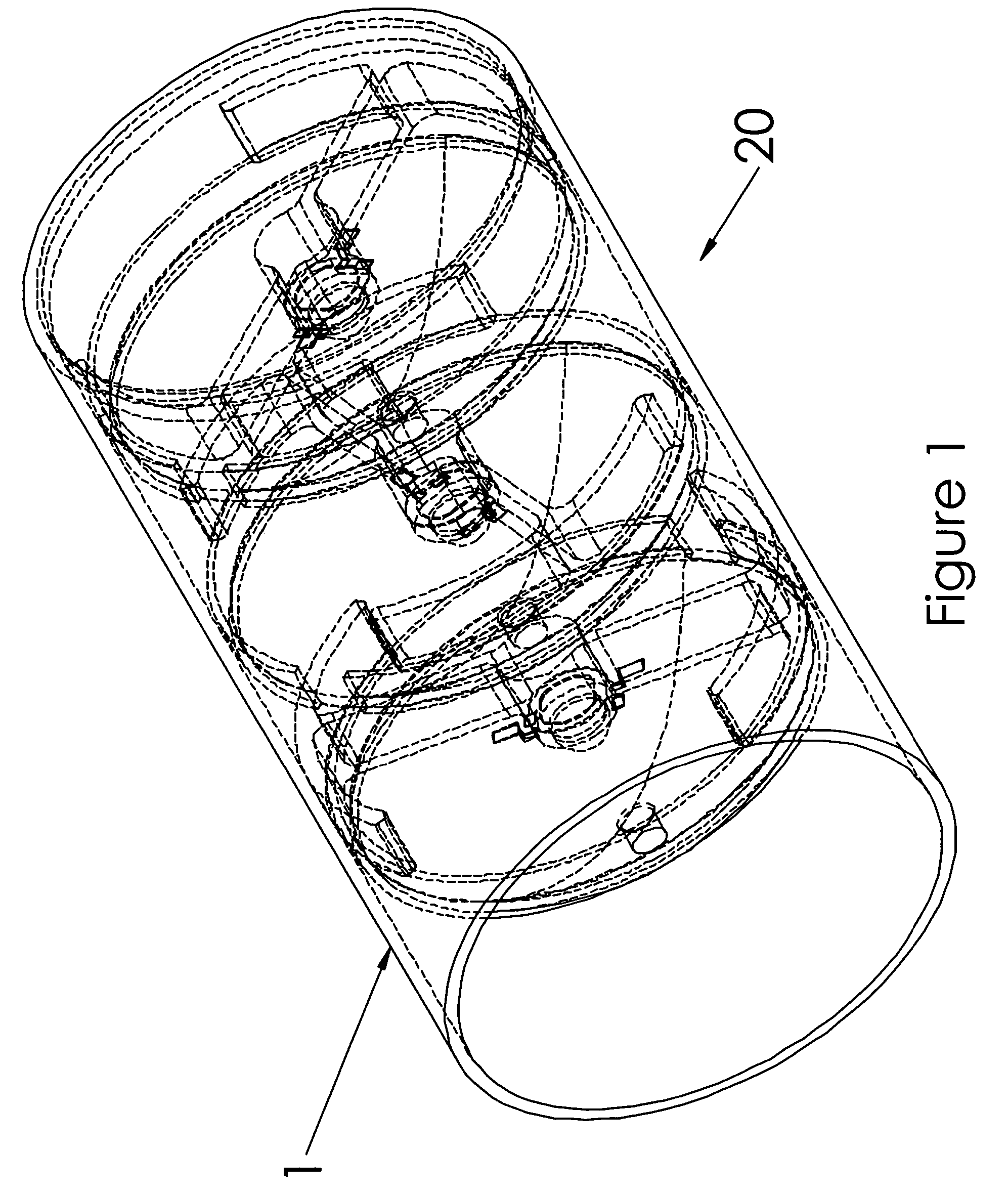
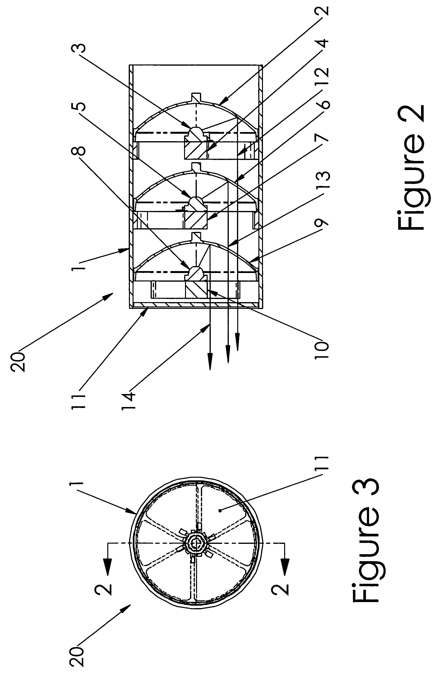
[0028]Turn to FIGS. 1–3 wherein the illustrated embodiment of the invention is depicted. FIG. 1 is a perspective view of the device, generally denoted by reference numeral 20, which is comprised of a housing 1 and various optical elements described below. Housing 1 in the illustrated embodiment serves to align the various optical elements of the device. One of the optical elements is a reflector 2 which is disposed in a rearward position of device 20 as shown in the left end portion of the side cross-sectional view of FIG. 2 and which can be coated to reflect substantially all the light from light emitting diode, LED, 3, which is held in position over reflector 2 by means of a heat sink 4. By LED it is understood to include a solid state light emitting diode package, which includes a semiconductor substrate in which the light emitting junction is defined, electrical leads, passivation layers and a lens or lens assembly mounted on or forming part of the passivating package around the...


PUM


Abstract

A plurality of light sources, each radiating a color of light; a corresponding plurality of reflectors are arranged and configured so that the reflector reflects light from a predetermined one of the plurality of light sources. The reflected light from the plurality of reflectors is mixed to generate a composite light from the plurality of light sources. A sequenced or stacked array of the light sources and dichroic reflectors mixes the reflected light from the reflectors. Each reflector is positioned on a common optical axis with an aligned corresponding one of the plurality of light sources to provide a light source and reflector pair. Each reflector is coated with a dichroic filter material which reflects the color of light radiated by the corresponding light source of the pair, and which transmits light radiated by all preceding light sources in the sequenced array.

Description

RELATED APPLICATIONS[0001]The present application is related to U.S. Provisional Patent Application, Ser. No. 60 / 491,694 filed on Aug. 1, 2003, which is incorporated herein by reference and to which priority is claimed pursuant to 35 USC 119.BACKGROUND OF THE INVENTION[0002]1. Field of the Invention[0003]The invention relates to the field of apparatus and method for using light emitting diodes (LED) or other light sources of differing wavelengths in an approximately unitized beam, sharing similar angle space.[0004]2. Description of the Prior Art[0005]Color projection systems have been used for many years to project motion pictures and still photographs onto screens for viewing. More recently, presentations using multimedia projection systems have become popular for conducting sales demonstrations, business meetings, and classroom instruction. In a common operating mode, multimedia projection systems receive analog video signals from a personal computer (“PC”). The video signals may ...

Claims


Application Information

Patent Timeline
Patent Type & Authority Patents(United States)
IPC IPC(8): F21V9/00F21V9/08H04N9/31
CPCH04N9/3197H04N9/315F21V9/08F21W2131/107F21W2131/406
Inventor RHOADS, GREGHOLDER, RONALD G.
Owner SIGNIFY HLDG BV
Learn More